My 2004 Laredo keeps draining the fuel out of the lines over night. It's worst when it's cold. I've been looking at o-rings, but then found diesel along the bottom of the pump (described elsewhere in the forums as "sweating." I decided to bite the bullet and rebuild the pump. Replacing the pump was not cost effective (hundreds of dollars and probably over a month to wait for it to ship from Europe to Kyrgyzstan). I opted for a rebuild kit which incidentally is one number different from the number listed in the parts cheat sheet. This one was Bosch F 01M 101 456. It was available from a guy in a shipping container in the local parts bazar for about US$30. I haven't reinstalled the pump yet to verify that everything works, but the pump may not be the ultimate problem, we'll just have to see. I had trouble finding a lot of info beyond replacing the pump so I figured I'd take pictures along the way and post a step by step. Use at your own risk. I'll update as reinstall the pump and find out what works.
First the oops...be careful with the connectors, I broke this one off on the low pressure pump...so much for fiddling with plastic at -5 degrees C.
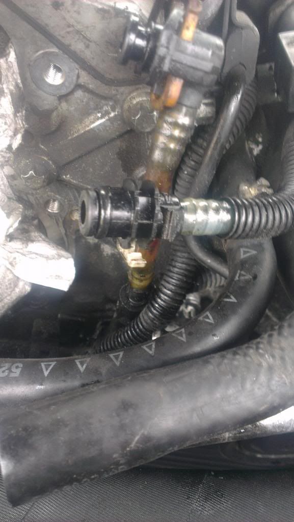
Still have to figure out how to rig or replace the connector. It's on the suction side (filter to low pressure pump).
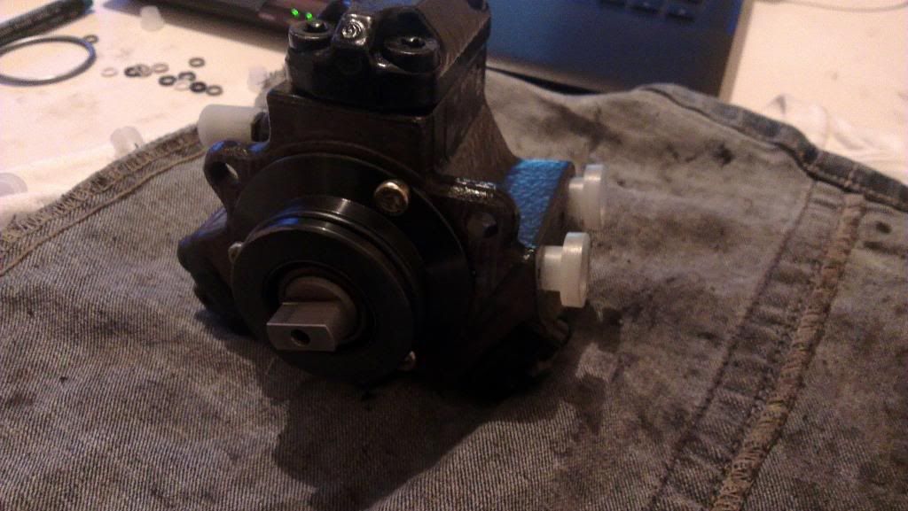
There are three bolts holding the high pressure pump in place. The last can be removed without removing the serpentine belt if you pull the disconnect fuel lines out of the way. After worming the pump out is where this write-up really starts.
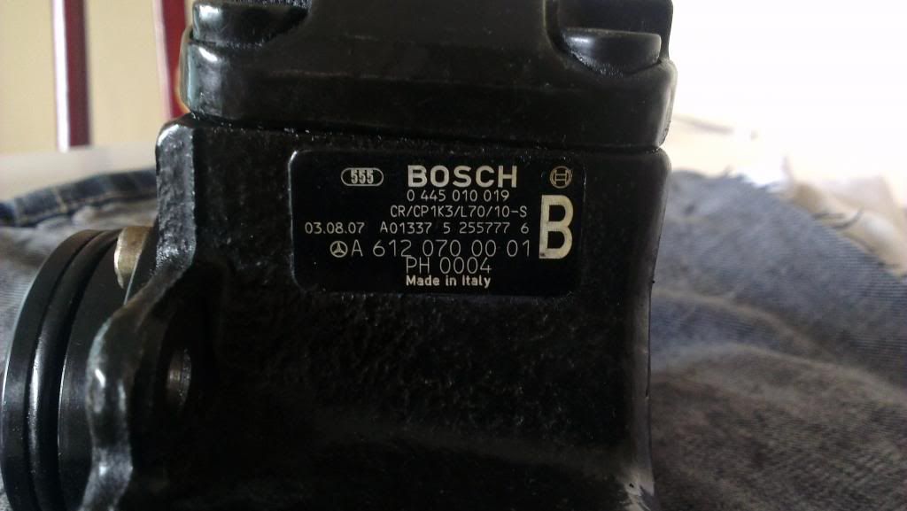
Model number on the pump:
After some experimentation I found it easiest to start with the "heads." (I did take out the three T30 Torx screws that retain the center cam but left the cam in place.) Take the screws out of the head carefully because it's under spring tension, so keep some down pressure. The screws on mine were T40 Torx. I numbered each head and each connection point on the body with a permanent marker. The fuel remnants tended to erase the marker, but I just redid them twice and it wasn't a problem.
Head bolts out:
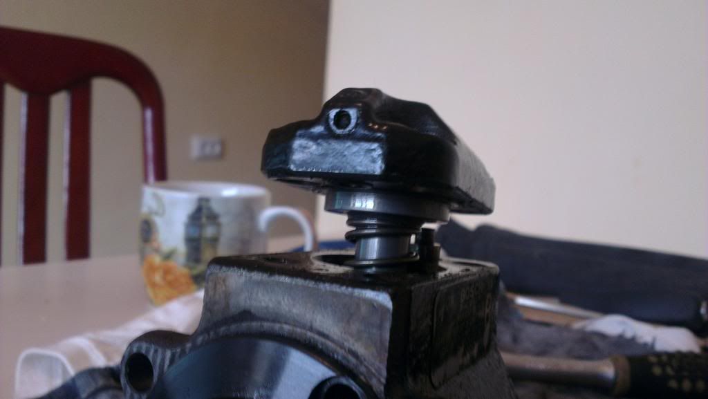
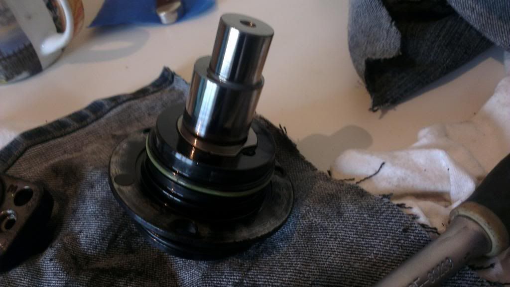
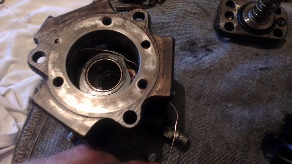
After removing the heads, I gently pried out the center cam assembly. I left it intact as the parts were not included in the rebuild kit. There appears to be a spring tensioned oil type seal on the outside. As I said, I did not disassemble it further. Be careful when you remove the assembly as there is a spring loaded piece inside that will launch. Inside the center you will find just the spring loaded assembly and the center piece (can't think of an appropriate name at the moment) which has three flats to interface with the pistons.
The center cam assembly removed:
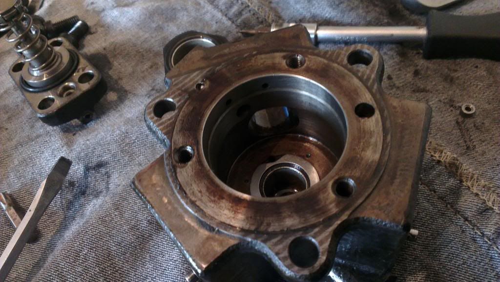
The empty body with the center piece with three flats slightly visible above it:
The spring loaded part:
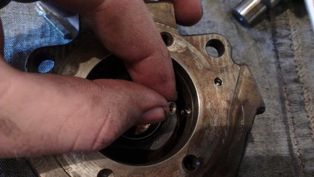
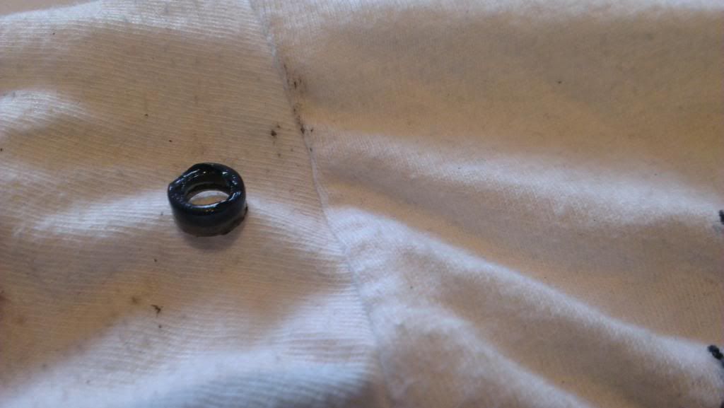
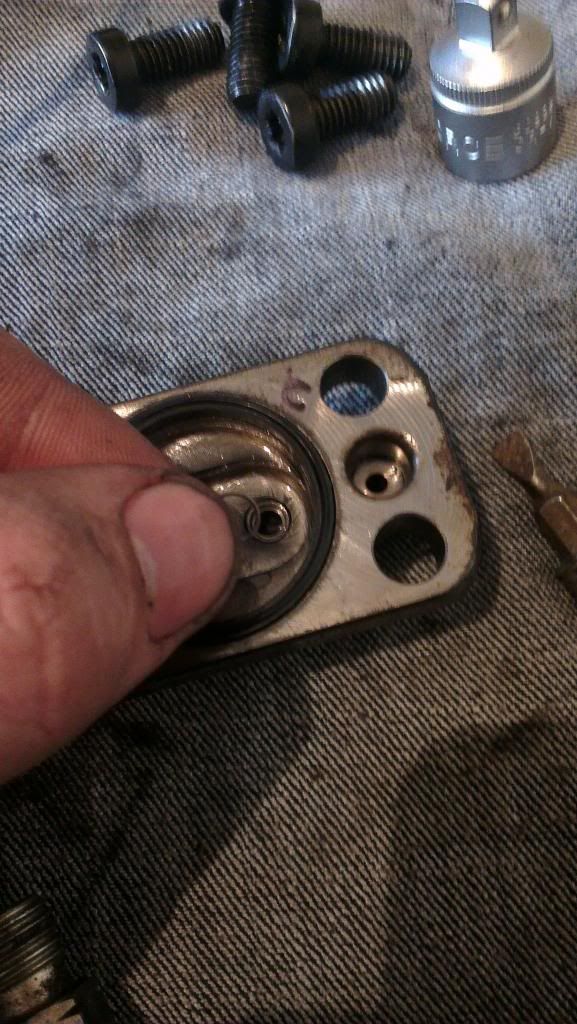
Replacing O-rings: I started with the "heads." There are two on one side and one on the other. The one should be attached to the head. The two are buried in a hole on the head. After fishing them out I put the new ones on the post/tube sticking out of the body. The two appeared to be a hard plastic ring on the body side and a softer rubber ring on the head side. My kit came with 6 white teflon rings and 6 coated ones. Originally I though to put a white one and a coated one, but then I realized the rubber one that came out looked more like a crushed o-ring than a harder flat one, so I put a coated rubber o-ring on the head side of each. One of the ones that came out was damaged, maybe that's my problem, but it seemed kind of small.
Showing the two that came out of the whole. Note the single black one on the other "head" in the top left corner:

The damaged o-ring:
Stacked up new o-rings:
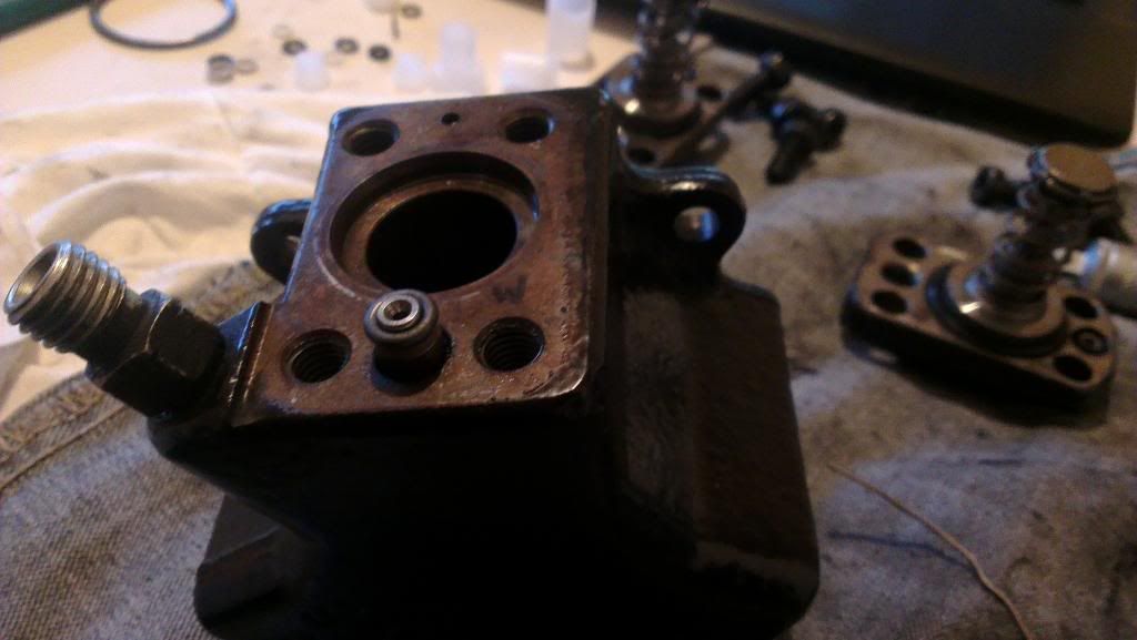
In addition to the small o-rings on each side there are two in the center: a large rubber one, and a small metal one. The large one seals the head to the body, and the small one seals the top of the piston assembly into the head.
large rubber and the small metal o-ring:
I replaced the two green seals on the cam assembly where it connects to the body. Then I put the the assembly back in. Because I don't have the tool to take out inside c-clips, I didn't disassemble the small parts that are behind the spring...I don't think they affect anything that would matter to me (at least let's hope so). I put the spring in then the metal top piece:
Then I used a straightened out paperclip to keep it in place until I had enough of the cam assembly in to retain it. Don't forget the flat sided center piece that interfaces with the pistons.
After that the heads go on carefully. Make sure the top piece of the piston/pump fits correctly into the hole with the metal o-ring. Gently place everything into the body and make sure all o-rings are retained and not pinched. Cinch down the bolts and you should be done. Finally replace the o-ring on the outside of the cam assembly where it goes into the engine cover.
Ok, no guarantees on this all because I don't have a manual that explains the procedure well. Hopefully the pictures help someone out. Feel free to add more details below!