Quote:
Originally Posted by JeanLuke

It's not the best, but both are radial flow impellers. Larger garage vacuums like mine are not fans but definitely radial flow blowers. ASME defines fans, blowers and compressors by pressure ratio. You are correct that the compressor side of a turbocharger is a radial compressor, not a fan or a blower. My garage vacuum is a blower. So, yes, it's not the best analogy but it's all I had.
Moving on...
As I said, the key is mass flow. As you correctly pointed out, for air mass flow depends on both volume flow and density. These are mathematically related by the universal gas equation - PV=nRT. (Google that one, it will take pages to explain.)
With a radial flow device, reduce the mass flow and the power reduces. That is a fact of how they behave - look up any radial flow device performance curve. Adding pressure differential = reduced mass flow = reduced power. To be 100% clear, this applies only to radial flow devices. It does not apply to axial flow (think of propellers). They behave very differently.
For an example, look at a typical radial-flow compressor performance curve here: https://www.ingersollrand.com/en-us/...turbo-air-2000
Notice how the power decreases as the flow decreases?
That particular model had a vaned diffuser. Our compressors have volute diffusers. They do the same thing, convert kinetic energy into pressure following Bernoulli's equation. |
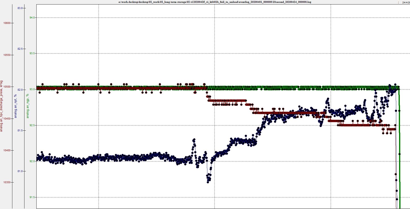
Below is an example of my old work. This entire scenario is based around constant input power.
This is an engine driving a compressor through a fluid coupling. This allows the compressor speed to do whatever it needs based on its own load.
In this graph, engine speed can be seen to remain constant. So input power is remaining constant. As the discharge pressure is lowered (controlled by people), the compressor speed (NPT) rises (Compressor unloads). As a result the opposite would be true. As the discharge pressure rises, the compressor speed would lower. This was a common and well know occurrence across the fleets I used to analyze.
They used to start these machine in a way I disagreed with. They would have everything in manual. Set the engine speed to a fixed value. Get plenty of distance away from the surge line, then load the compressors by the use of the control valves. The result was a increased discharge pressure, reduced compressor speed, and unit approach to the surge line. Then they would increase the engine speed, resulting in an increased compressor speed, and repeat the process. The system has an auto button which worked well, but the old boys just liked doing it this way. No harm was done.
If input power remain constant, and the discharge is slowly blocked off, the wheel speed will lower. The combination of increased discharge pressure and reduced RPM brings the unit closer to the surge line. At the point of surge, the flow temporarily reverses and the speed falls violently. Now though the discharge pressure is low, the speed increases again, the surge margin increases and the discharge pressure builds. This then causes the wheel to slow down and the surge cycle to continue.
If in a constant input power situation, the wheel speed increased as discharge pressure increased, then the compressor would move further to the right and away from the surge line and be less likely to surge. This doesn't happen.
I am happy to just agree to disagree on this one.