Grand Willys Project - Page 223 - AUSJEEPOFFROAD.COM Jeep News Australia and New Zealand

Go Back   AUSJEEPOFFROAD.COM Jeep News Australia and New Zealand > JEEP GARAGE > Jeep build up
Register Forums Trading Your Jeep My Garage Mark All Read

Post New Thread  Reply
 
Thread Tools Search this Thread
  #1555  
Old 10-11-2019
Gojeep's Avatar
Gojeep  Gojeep is offline
LokRinger
 
Join Date: Jul 2002
Location: Victoria
Posts: 6,876
Likes: 791
Liked 1,765 Times in 558 Posts
Default


Time to sort out the handbrake. I had drilled out all the spot welds from where the cables came into the cab under the donor's back seat. The threaded boss was where the fuel tank strap bolted in which you can see in the background on a separate bracket now as the fuel tank is only supported by the chassis and not the body.


Mounting the handbrake was easy as just bolted straight back where it was inside on the donor floor pan.


I ran the cable through the rear wall after fitting a grommet. It was easy to know where to mount the plate as it had to go directly over the existing fuel tank strap mount. The bolt even threaded into the original boss as well. Cables just hooked up as before and didn't even have to adjust the handbrake!


I also changed the resonator slip over couplings to V-band ones. I tig welded them on the inside only.


I did this to make it easier to drop the resonators out when changing the battery from below.


Working on connecting the steering shaft to the rack. As I moved the axle forward 175mm, (7"), I need a longer shaft. The hypotenuse length would have changed by 160mm, (5.25"), so that is how much longer the shaft needs to be.


The top shaft is what comes through the firewall and is collapsible by shearing a nylon pin in the event of an accident. The bottom connects to that to go to the rack and has a sliding section to take up any normal flex.


In Australia we are not allowed the cut and weld steering shafts without the added expense of the weld being x-rayed and certified by an engineer. So I went to the wrecking yard to pick up another Jeep shaft from a KJ Cherokee of the same year hoping I could use parts from that. It is the shorter, lower one of the two.


I figured that I could flip the Cherokee one and use the upper section for a new lower one as it was longer than the Grand Cherokee lower one. Was about 50mm, (2"), longer than I needed but have a plan for that.


I drilled out the nylon pin from the upper section, on the right, and pulled apart the sliding section to use the rubber boot from the lower part. What I am doing is turning the upper section into a sliding section and the extra length I don't need simply rides up further inside.


Now, to join my new piece to the Grand Cherokee upper, I had to remove the uni which is staked into place. I thought it would just push past the stakes but it popped the top of the uni cap right off instead! Fortunately this was not the uni I was going to use as I was just trialing my procedure


So I drilled the stakes being careful not to drill into the caps or take too much from the shaft ears.


The last little bit after this I used a small cold chisel to chip away the remainder. You only need to do one side.


Soaked some WD40 on the caps and picked a socket just smaller than the cap for the staked side and another just bigger to press the other side into.


Carefully pressed the uni cross across as far as it will go to the other side. Tapped the ears to help it move any time the pressure increased. Then removed the cap so I could remove the uni itself.


Once out the reverse was done to install the other shaft to it just like changing a driveshaft uni. I restaked it by squaring off a nail punch and then hitting it in different spots than before. I supported the opposite side cap to make sure it didn't try to punch out the other side.


So the old KJ Cherokee upper is the new sliding lower of the WH Grand Cherokee. It was well greased with marine grease and then the boot was fitted to keep out water. It slides as freely at the original lower section without any sidewards play


Slipped on the bearing support in the same place as when on the donor. Will mount it off the inner guard once I make them.


There is plenty of clearance with a minimum of 40mm, (1.5"), all round.


The running angles are actually less than stock as the shaft is now longer than before.
__________________
Cheers, Marcus.

My web site:
http://willyshotrod.com Over 5'000 Club
Likes: (6)
  #1556  
Old 16-11-2019
Gojeep's Avatar
Gojeep  Gojeep is offline
LokRinger
 
Join Date: Jul 2002
Location: Victoria
Posts: 6,876
Likes: 791
Liked 1,765 Times in 558 Posts
Default


To finish off the steering shaft I needed the column in place. Think this is the first time it has been fitted! To bolt it in I needed to refit the donor dash support frame which meant the A/C had to go in first and the brake pedal box to save pulling things to fit them later on.


Fitted the booster for the first time too and all just bolted in perfectly. The column is not only tilt but reach adjustable, I had to take both that into account before fitting the bearing support. The steering shaft actually pivots slightly through it when you adjust for tilt. I just made a simple bracket off the frame for a stronger support and to make it easier to remove the guard when necessary.


Back to the grille again. I have the turn signals chosen so had to fill in the stock holes as the new ones are a flush mount.


The filler piece I just made round and used some copper under the slots to fill them in.


Just used the mig this time as just do what my mood dictates sometimes.


Notice how much the metal rose due to the weld shrinkage. Like making a pleat or dart in material. I like to grind the bulk of the proud weld off top and bottom first before doing any hammering on it. Less material to move and the slower heat and cooling of the grinding help anneal or soften the metal a bit. Far from a full annealing process, but it can't hurt either. I dont have the weld cracking on me either during planishing.


Just by hitting hammer on dolly in the HAZ, heat affected zone, it is already almost perfectly flat.


Only now do I take the weld down to perfectly flat, because if you do that before hammering, you end up with a circle of thinner metal. Final planishing was done with a flipper and dolly.


I had spotted these turn signals on a great looking Willys Panel Delivery of Sam Hacker. He was kind enough not only tell me where he got them, but to then buy and send them to me as well.


They are a quality item with chrome plated cast steel ring and not just cheap plastic. They have 17 LED's and the circuit board is epoxy coated to keep it waterproof. Made by United Pacific to fit 39 Chevy Sedans. https://truck.uapac.com/product/cont?pid=11383


At just over 75mm-3" in overall diameter, they are between the early and later stock ones in size.


I like how they mimic the headlight bezels for shape too.


I am thinking of getting another set for the rear in both amber and red.
__________________
Cheers, Marcus.

My web site:
http://willyshotrod.com Over 5'000 Club
Likes: (5)

Last edited by Gojeep; 18-11-2019 at 06:40 PM.
  #1557  
Old 01-12-2019
Gojeep's Avatar
Gojeep  Gojeep is offline
LokRinger
 
Join Date: Jul 2002
Location: Victoria
Posts: 6,876
Likes: 791
Liked 1,765 Times in 558 Posts
Default

More boring but necessary work going on.


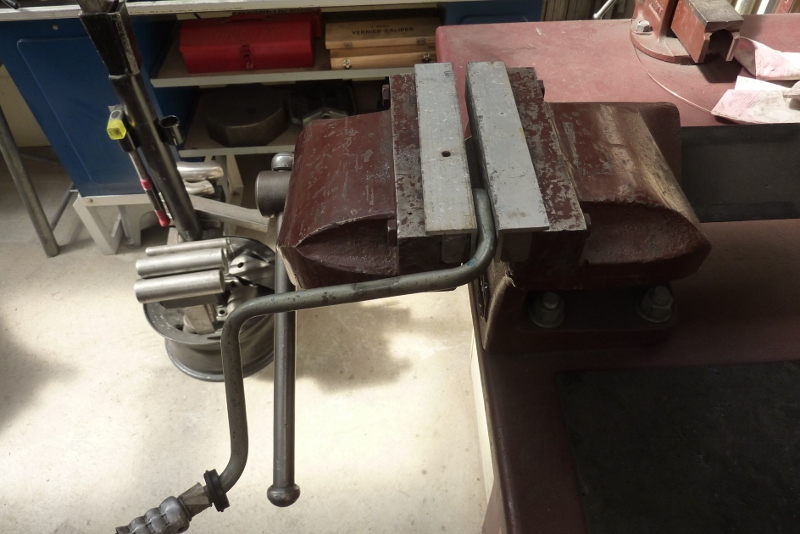
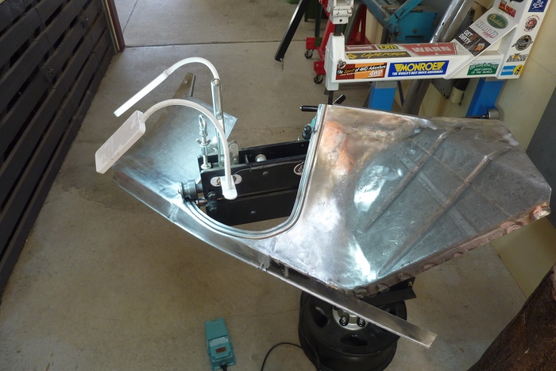
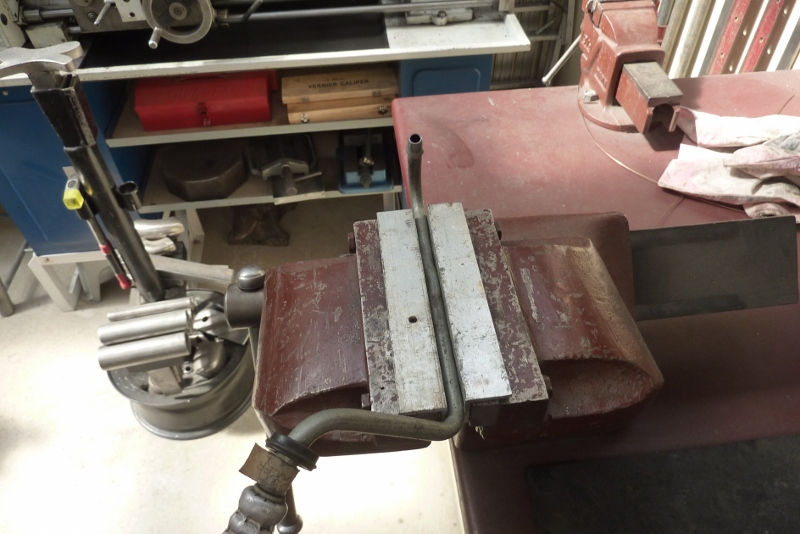
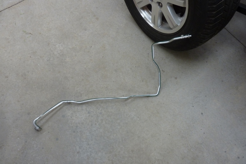
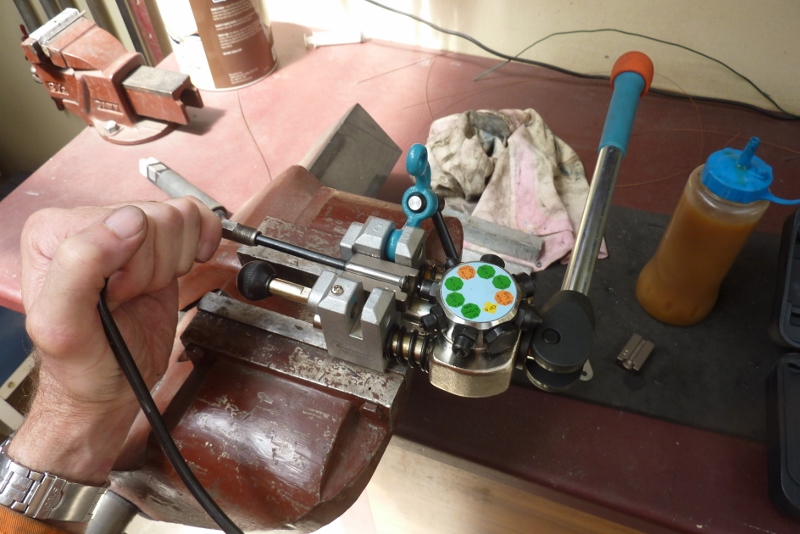
Doing some more plumbing. These are the 3/8" steel OEM transmission lines. I'm just showing one of the techniques for straightening bends I use. Just clamped between some aluminium angle.


I just push a little bit at a time, then move the line in as far as it will go into the jaws each time. The squared part of the line before the bend is where the factory separation clip goes.


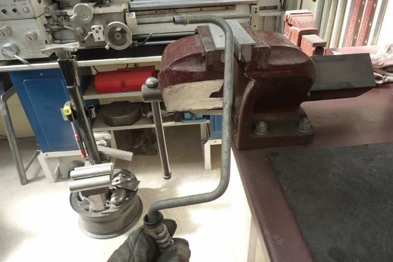
This is what happens if you push to far between reclamping, You get secondary bends happening causing a dog leg.


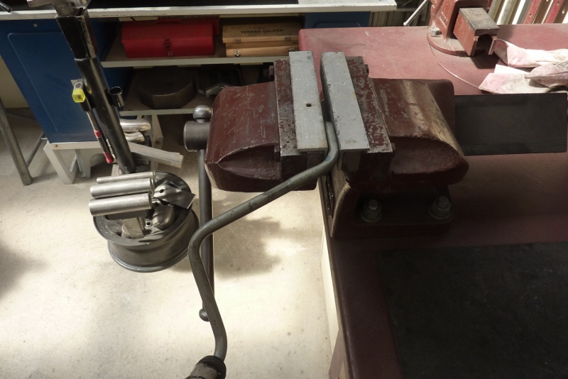
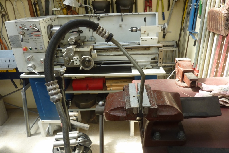
Once the bend is reduced to about 15-20*, I bend it straight in the middle of the jaws. Rotate and re clamp until it is straight all around.


Not show class, but more than good enough for what I am building. The bend was halfway between the squared part and the top bend.


The top bend was facing the wrong way. I could straighten it and then bend it the other way.


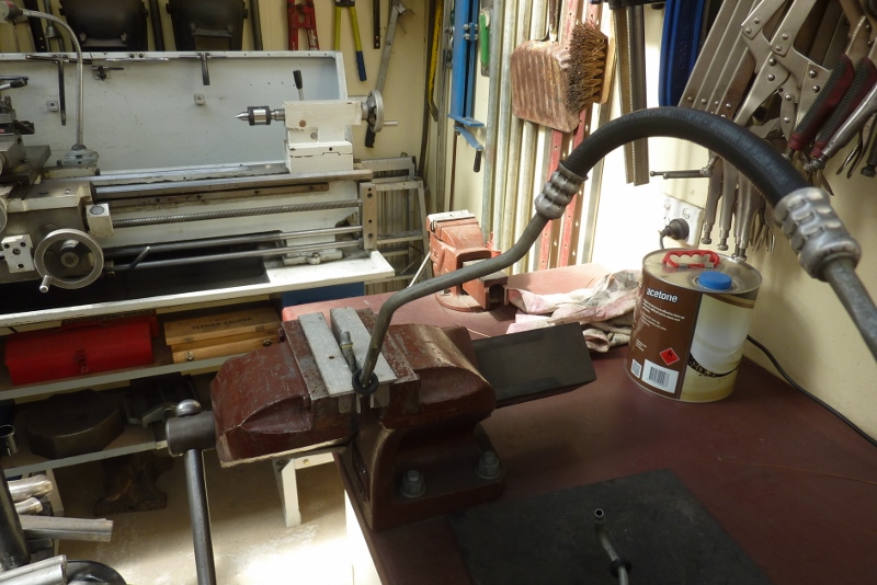
But when it has a long section before the next bend, I just twist it instead.


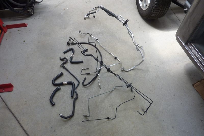
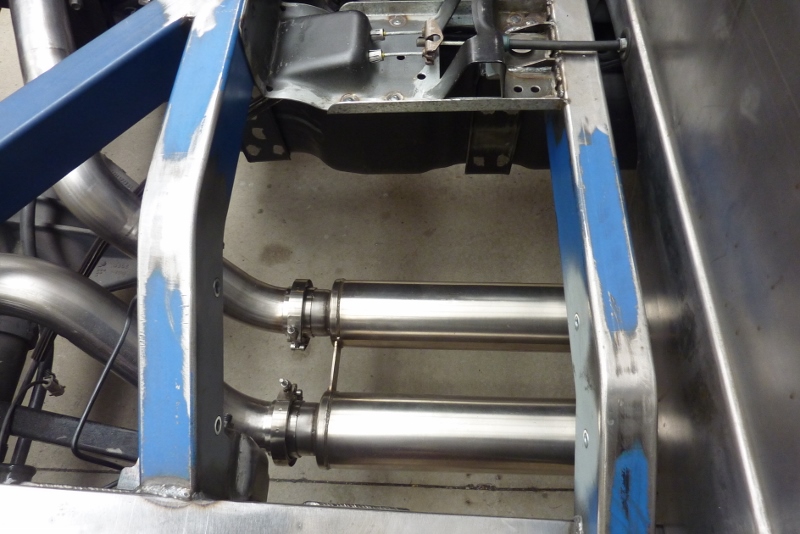
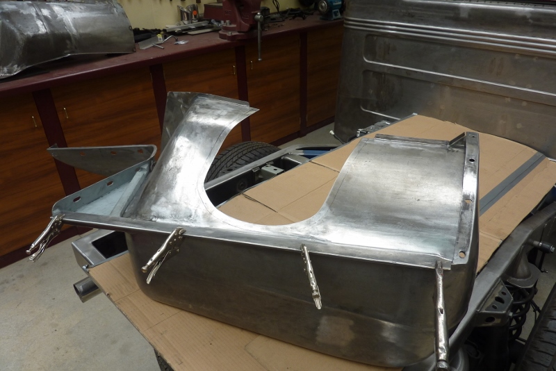
I now have the fuel lines run all the way as well as the transmission lines and the complete rear brake system. Still have all this to go though!


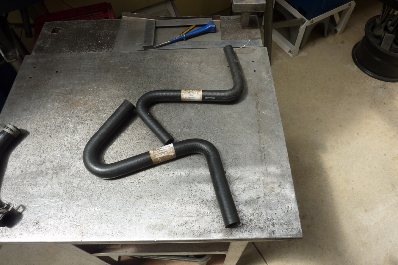
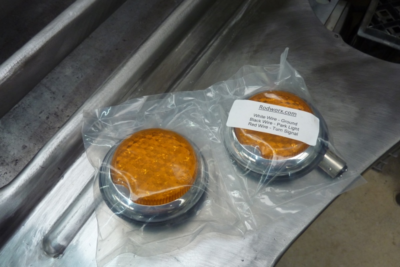
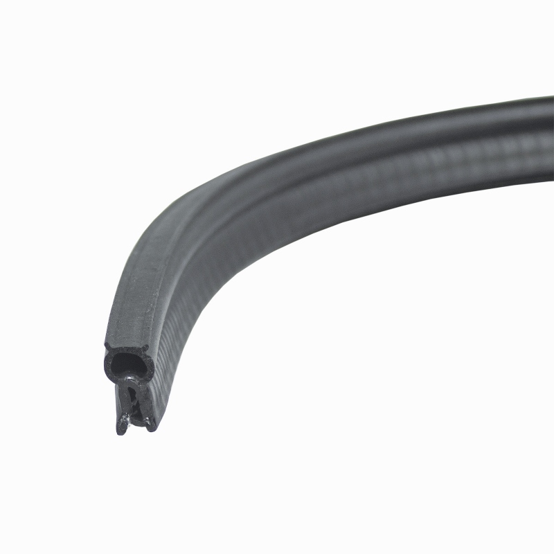
Thought I would share these hoses. They call them S hoses and are made especially for custom/universal applications.


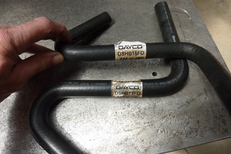
They come in a variety of diameters and the FO on the end of the part number means these are for Fuel and Oil. They have cheaper water/vacuum versions, but you should never use them for fuel and oil!


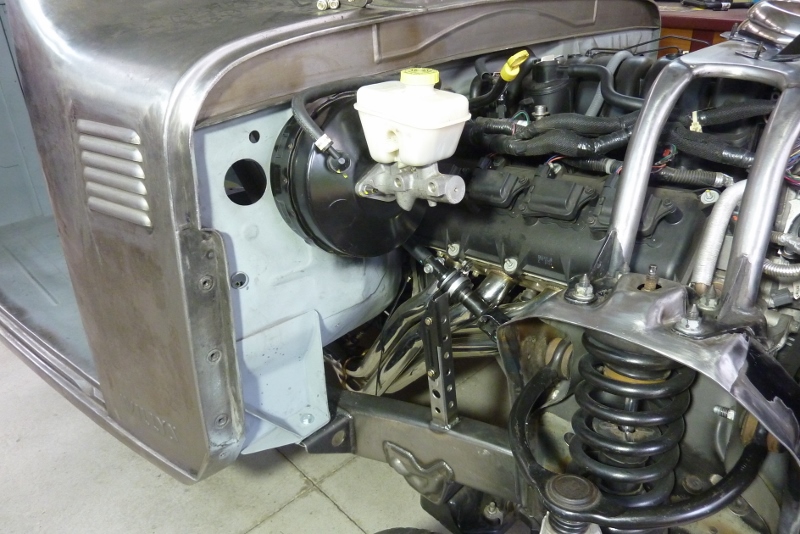
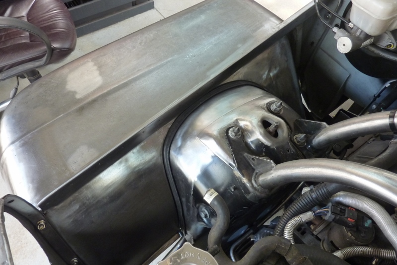
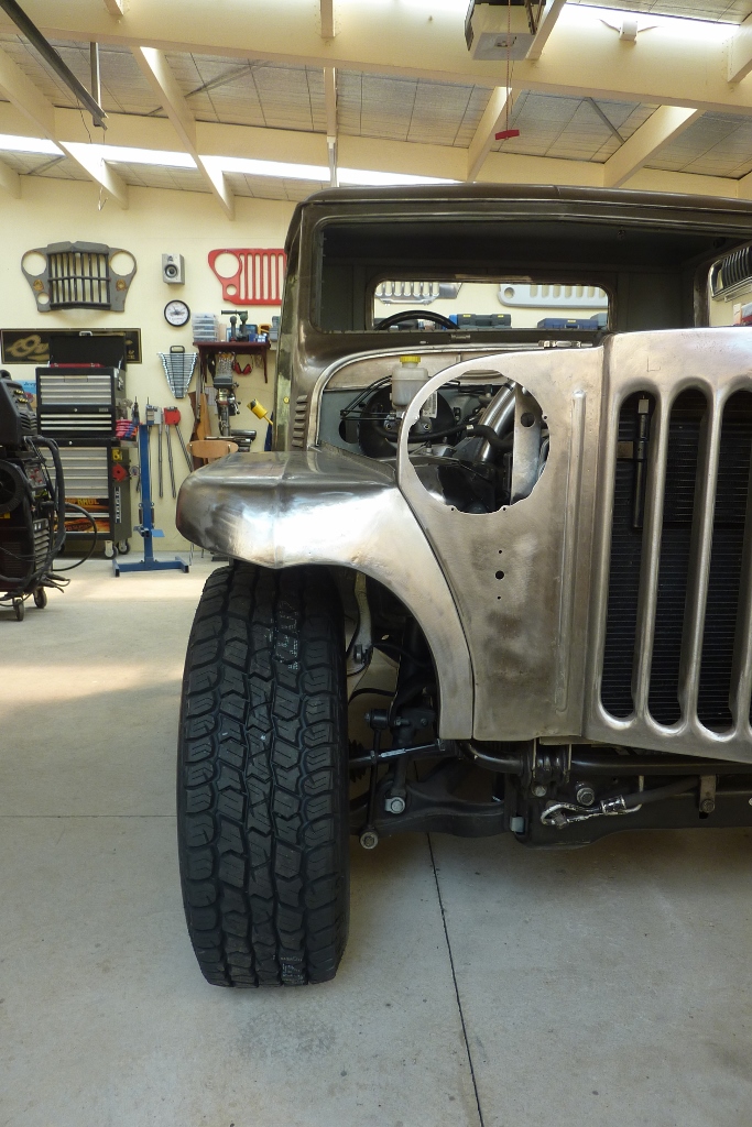
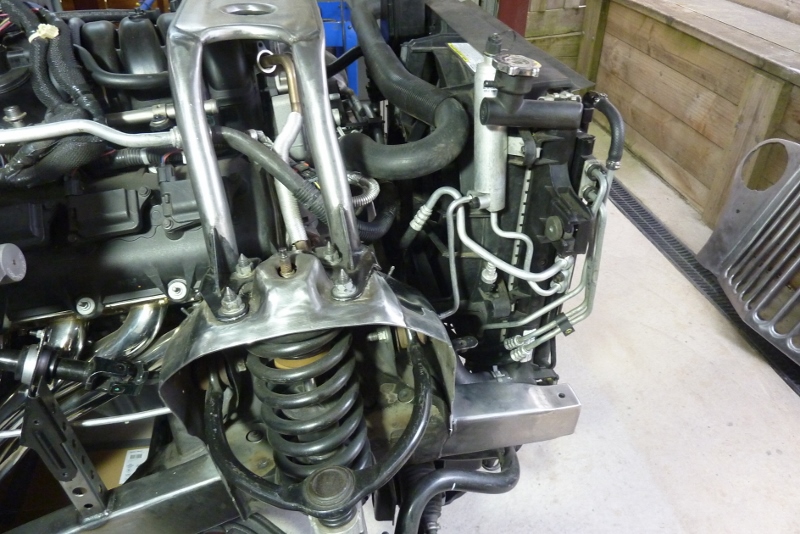
I bought the 19mm-3/4" version to replace the power steering pump return line. You can see how much lower I have mounted the radiator than it was in the donor. It is closer as well.


I cut one of the bends off and fitted it. I was lucky with the donor top radiator hose as that just fitted right back on again. The bottom hose I had to shorten from both ends losing one of the flared end sections. I soaked the hose in boiling water to soften it and then quickly pushed it over a steel pipe slightly larger than the radiator outlet to expand it back up again. Then let cool.


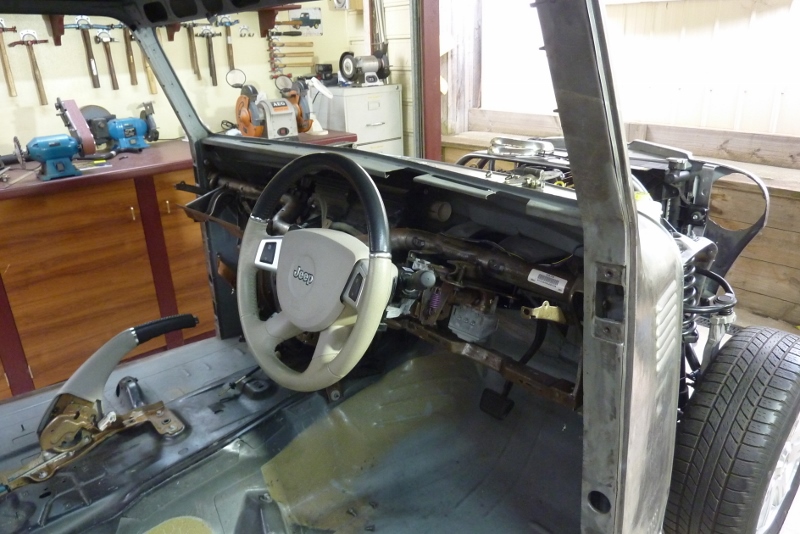
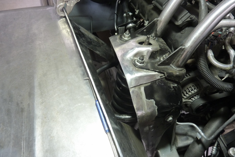
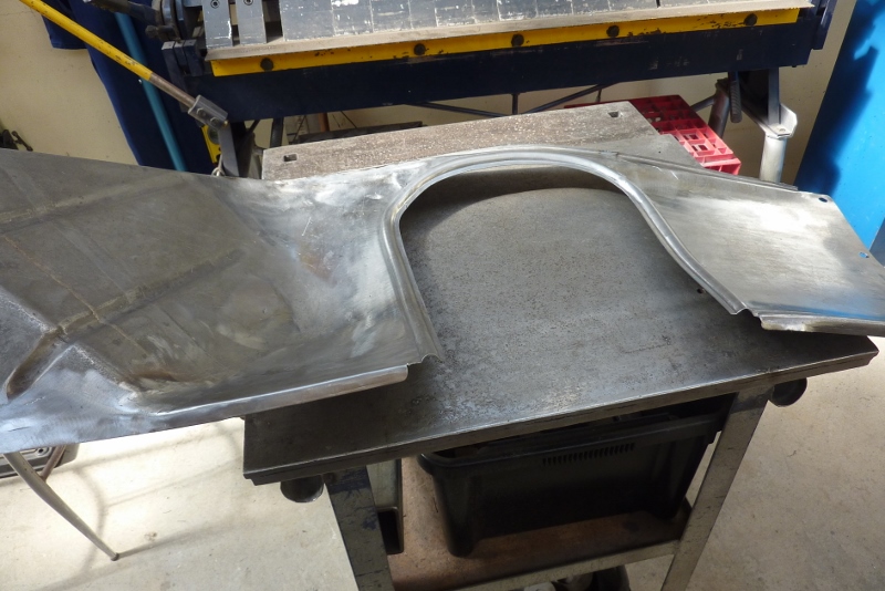
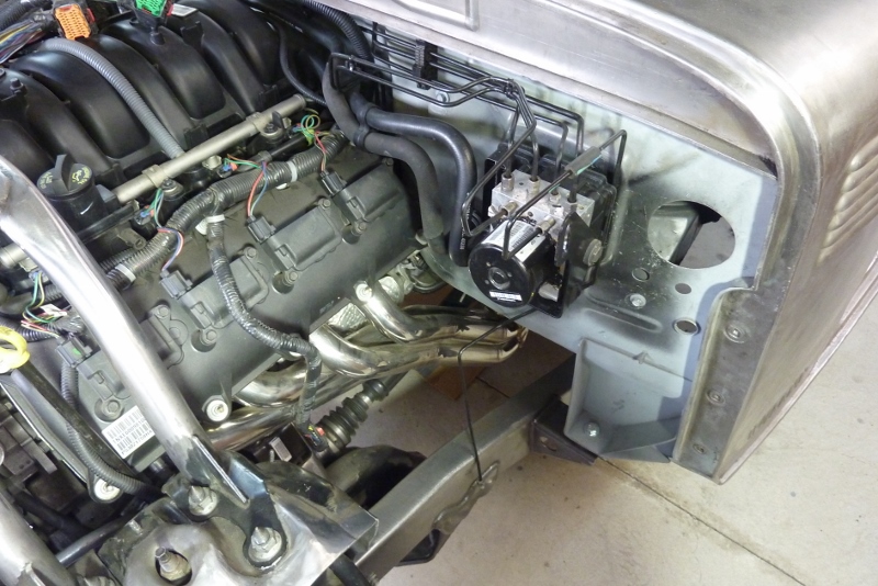
Some of the more complex pipes that I was re-routing was this A/C line. I found it easier to make a template from wire first to see if I could use any of the factory bends in the new location rather than straightening it all out and starting again


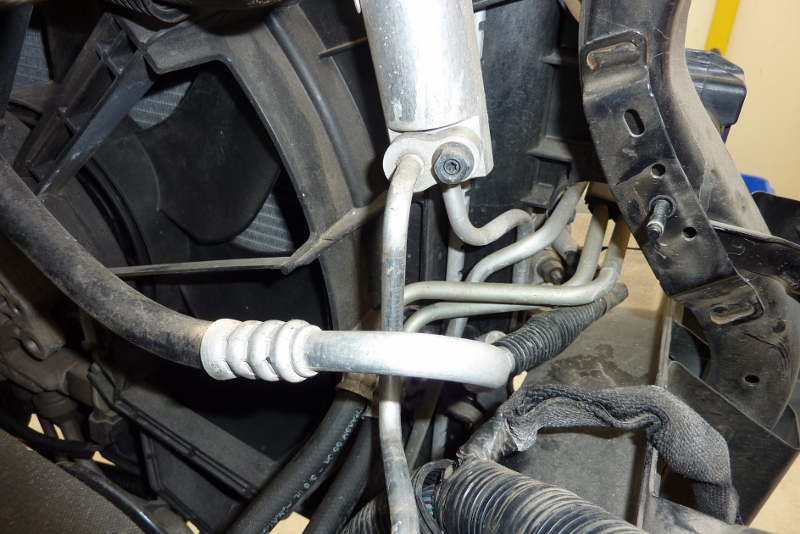
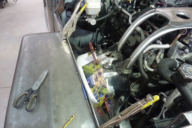
This is the photo I took of the donor before pulling it apart so I knew where everything went! Even though I am making it look OEM, I try to neaten it a bit where I can.


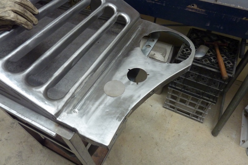
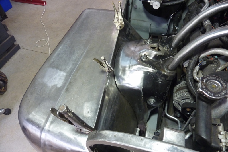
This was I ended up with while also leaving as much room as possible for other things like the airbox and radiator overflow that was mounted on this side.


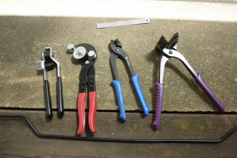
For working on the brake lines I used these tools. Rarely the centre two though as they both mar the plastic coating of the OEM lines.


I like these 3/16" line straighteners that I got from Eastwoods. I did however have to modify them so that the leading curve was at both ends rather than just one.


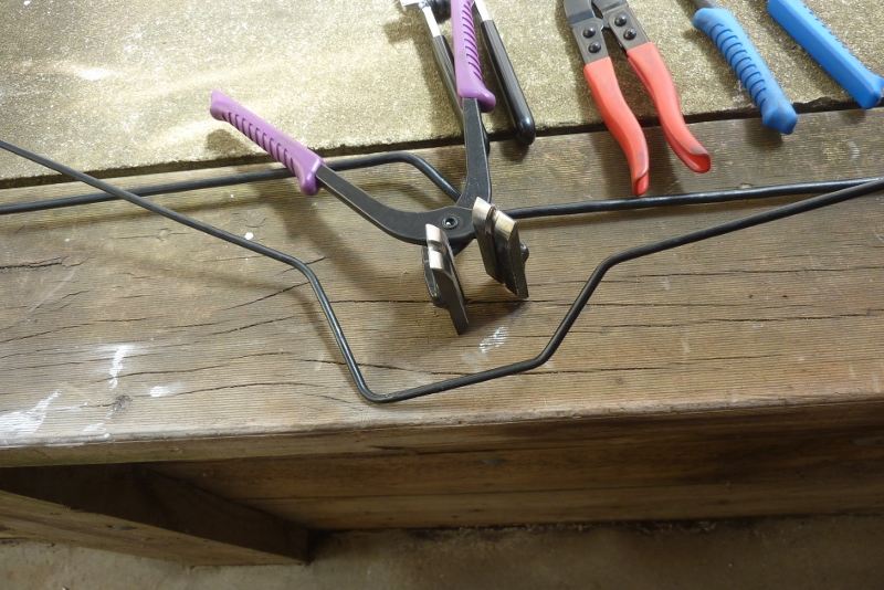
Just place the bend in the middle of the jaws and squeeze them hard. So long as the bend is less than 90*, they will work. Just stretch out those bends a bit first by hand that aren't.


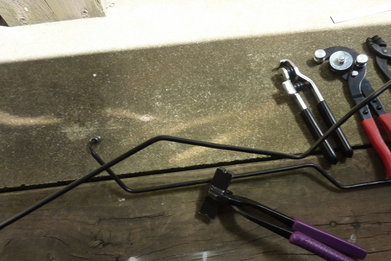
That is the result of the bend gone between the remaining ones. I got a bit more improvement than this, if when squeezing hard, I hit the centre over the jaws with a nylon mallet while it was supported over some timber.


Lines that were shortened were re-flared with the Eastwoods tool. I was a brake mechanic many years ago and this is better than what we had back then.


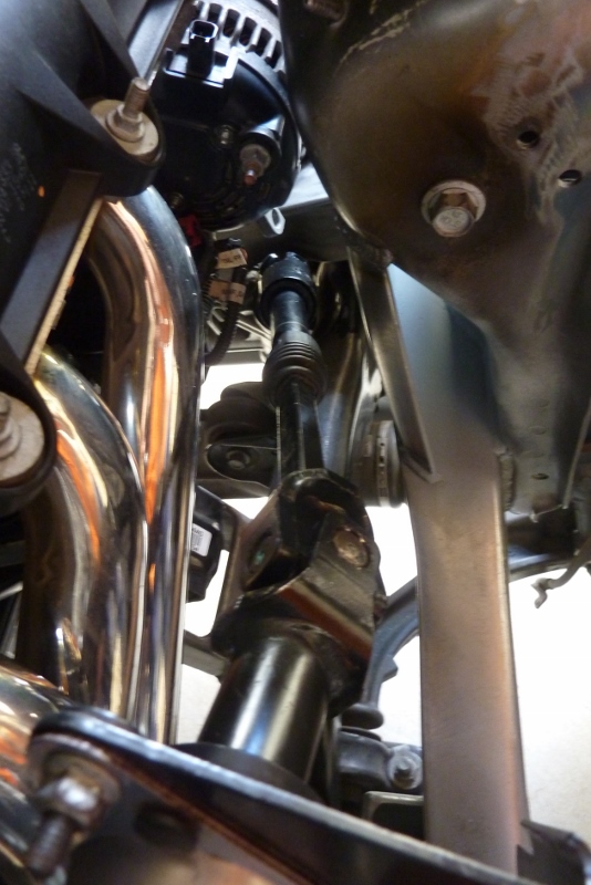
A nice little trick I first saw 20 odd years ago, to separate ignition wires originally, was to use zip ties as a separation clip. First loosely loop over the two lines, then use a second zip tie around that tie between the two lines as a spacer.


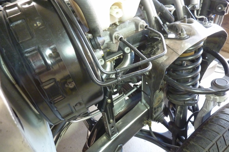
Tighten the spacer zip tie fully before then tighten any remaining slack out of the other tie that is inside of it. One ready made line spacer. The line bends over the booster BTW were made with the first tool shown and the right bends were factory.


I have not done badly on using the OEM lines considering that I have 8.5" longer wheelbase than the donor Grand Cherokee and 7" of that is the front axle further forward of the firewall. Only the shortest line from the ABS pump to the nearest front wheel will have to be replaced if I want to keep the stock routing of going via the firewall first.
__________________
Cheers, Marcus.

My web site:
http://willyshotrod.com Over 5'000 Club
Likes: (5)
  #1558  
Old 21-12-2019
Gojeep's Avatar
Gojeep  Gojeep is offline
LokRinger
 
Join Date: Jul 2002
Location: Victoria
Posts: 6,876
Likes: 791
Liked 1,765 Times in 558 Posts
Default


I have a large gap to fill between the inner guard and the suspension tower.


I was first going to form the inner guard towards the tower but thought it would be better to extend the tower towards the inner guard.


This is hot rolled 2mm, 14 ga, thick steel to match the tower. I formed the compound curve inside this 150 year old gold stamper base. The multiple radiuses it has means there is always one that suits. They were there from different stamp head changes over the years of use. I just cleaned them up


I have left a gap all the way around as the tower is welded directly to the frame and the guard to the rubber mounted body.


After marking where the tower sits, I cut an even amount in from this ready for bead rolling. If you bead roll with an even amount next to it, the bead will form more consistently as it draws metal in from the edge.


I prefer to bead roll with the female die at the top in the bead roller so you can use one edge of the die to accurately follow. Too much room for error if you try to estimate the centre of the male die. So I am measuring half the distance of the die bead width from the centre of the black line.


I also turned down the flat area each side of the male die so I could get a deeper bead. For some reason the Chinese dies only the female side is full depth, but not the male side! So you can never get a full depth bead and it also means that it doesn't stretch the metal causing more distortion. I went as far as I could with multiple passes from one side before feeding in from other to complete the bead.


Still had a little stretching of the bead to do to sit flat across the top, but otherwise it did a better job.


The bead was made for two reasons. To greatly stiffen the inner guard around the opening, but also to sit some pinch weld rubber with a single top bulb in it.


The rubber seal handles all the movement between the body and the suspension tower, while also stopping road grime and track mud from coming in there.


Looks good enough from inside the guard too I think.
__________________
Cheers, Marcus.

My web site:
http://willyshotrod.com Over 5'000 Club
Likes: (7)
  #1559  
Old 22-12-2019
bodgie's Avatar
bodgie  bodgie is offline
Rock Munki
 
Join Date: Aug 2009
Location: Castle Hill, NSW
Posts: 2,136
What Jeep do I drive?: WG
Likes: 11
Liked 300 Times in 245 Posts
Default

Nice job Marcus, very well executed in my opinion.
Likes: (1)
  #1560  
Old 18-01-2020
Gojeep's Avatar
Gojeep  Gojeep is offline
LokRinger
 
Join Date: Jul 2002
Location: Victoria
Posts: 6,876
Likes: 791
Liked 1,765 Times in 558 Posts
Default

Barely took a photo as was just repeating what I did on the other side inner guard.


But look what has finally been decided on. A new set of 5 wheels and tyres! These are American Racing AR969 Ansen wheels in 17x8.5" with +25 mm offset with 5x127 PCD to suit the Grand Cherokee donor axles. Tyres are Mickey Thompson Deegan 38 AT's in 265/70R17, (31.7x10.5").


A fair bit more truck like than the stock donor ones that is for sure.


Hotrod rubber rake! Couldn't wait before finishing the front, so quickly threw on a pair of rears.


Plenty of clearance to the frame rail. I liked the tread as more old school looking like a dirt track tyre. Modern tyres would look weird and didn't want the weight and noise/handling sacrifices of a mud terrain.


No problem with clearance to the swaybar. Tyre actually protrudes a couple of inches past the side grille.


One thing that did bug me with the wheel centre moved outwards, an inch each side over stock, is that the bottom of the peak no longer lines up with the middle of the tyre.


So first thing I did was hammer and dolly out the peak that ran three quarters of the way down the guard top from the bottom of the guard lip.


Came up pretty well considering no grinding, sanding, filing or shrinking was used. Just a paint strip disc to highlight what needed to be done. I was expecting to use the shrinking disc but there was more crown at the rear of the guard where there was no peak, so it was all the same crown in the end with the peak removed.


Then I hammered out the part that dipped down to give a smooth arc instead. Then trimmed back the excess from the lip to keep it even. Guard now looks even more like a hybrid between the flat nosed 48 and the later pointy nosed guards. Also removes the troublesome stress riser that the end of the peak created where they all crack in the end. So now have both inner guards finished and changes made to the outside as well.


I had my tyres fitted without any wheel weights. I prefer on my Jeeps, and even the camper trailer, to run stainless steel teflon coated balancing beads. They don't break down like the glass ones and I have been using them for about 10 years on my Cherokee without any problems and get better tyre wear. No ugly weights to see either! See my write up on my Cherokee if you want to know more. http://gojeep.willyshotrod.com/BalancingBeads.htm


I chose these tyres and wheels for the more old school smooth sides walls matching the wheels and 48 body. I looking for a classic looking wheel so billet was out and didn't want the extra 30% heavier weight of steel. 5 slotters were even offered from the factory on the Jeep J10 which took over from this body shape. These AR969's were also offered in a satin black which would give a more military feel to the build. Turns out there were none left in the country as they are no longer produced in this size, so was lucky to get any at all. Can always paint these later along with the body if it suits better, but might leave as is.
__________________
Cheers, Marcus.

My web site:
http://willyshotrod.com Over 5'000 Club
Likes: (3)
  #1561  
Old 19-01-2020
Gojeep's Avatar
Gojeep  Gojeep is offline
LokRinger
 
Join Date: Jul 2002
Location: Victoria
Posts: 6,876
Likes: 791
Liked 1,765 Times in 558 Posts
Default

Video update.

https://youtu.be/aP00wupoN_A
__________________
Cheers, Marcus.

My web site:
http://willyshotrod.com Over 5'000 Club
Likes: (3)
Post New Thread  Reply


Posting Rules
You may not post new threads
You may not post replies
You may not post attachments
You may not edit your posts

BB code is On
Smilies are On
[IMG] code is On
HTML code is On


All times are GMT +10. The time now is 10:38 PM.


Advertisements


AJOR does not vouch for or warrant the accuracy, completeness or usefulness of any message, and are not responsible for the contents of any message. The messages express the views of the author of the message, not necessarily the views of AJOR or any entity associated with AJOR, nor should any advice be substituted as technical advice replacing that of a mechanic. You agree, through your use of this service, that you will not use AJOR to post any material which is knowingly false and/or defamatory, inaccurate, abusive, vulgar, hateful, harassing, obscene, profane, sexually oriented, threatening, invasive of a person's privacy, religious, political or otherwise violative of any law. You agree not to post any copyrighted material unless the copyright is owned by you or by AJOR. The owner, administrators and moderators of AJOR reserve the right to delete any message or members for any or no reason whatsoever. You remain solely responsible for the content of your messages, and you agree to indemnify and hold harmless AJOR, the administrators, moderators, and their agents with respect to any claim based upon transmission of your message(s). The use of profile signatures to intentionally mislead or misdirect any member on this forum is not acceptable and may result in your account being suspended. Any trip that is organised through the AJOR forum is participated at your own risk. If you or your vehicle is damaged it is your responsibility, not that of the person that posted the thread, message or topic initiating the trip, nor the organisers of AJOR or moderators of any specific forum. This forum and associated website is the property of AJOR. No user data is harvested and no information supplied in your registration will be sold for profit.


Powered by vBulletin® Version 3.8.7
Copyright ©2000 - 2024, vBulletin Solutions, Inc.

AJOR © 2002 - 2024 AUSJEEPOFFROAD.COM. All corporate trademarked names and logos are property of their respective owners. Ausjeepoffroad is in no way associated with DaimlerChrysler Corporation or Fiat Jeep.
www.ausjeep.com www.ausjeep.com.au www.midlifemate.com ausjeepforum.com www.r9kustoms.com
vB Ad Management by =RedTyger=