Drover asked for it so here goes.
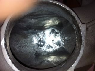
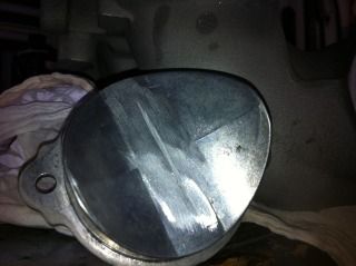
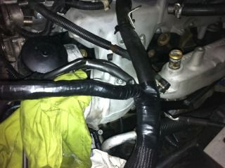
The basis of this modification is actually to fool the ECU into thinking the EGR is still functioning as all you actually have to do to disable the EGR is unplug the wiring connector. However the issue arrises that the ECU is monitoring the EGR function by looking for a change in airflow through the MAF sensor so this wiring mod is designed to alter the MAF signal when the EGR would normally be activated. Apparently the MAF senses the pressure change in the manifold when the EGR opens. It does not affect the normal operation of the MAF in all other circumstances. The operation of the EGR is a spring loaded valve activated by vacuum hence it is always shut unless the vacuum solenoid is triggered. It could be prudent to remove the EGR valve and make sure it is not stuck open but mine was a bugge rto ge out and I had my manifold off so I would say unless you think it is leaking don't bother. Because I had the manifold cleaning it out I removed the EGR and cleaned out the chamber and the valve itself then I machined the rear of the valve where it has a step, this removed about 2mm of material to ensure the valve was sealing as tight as possible. Then I decided I may as well remove the venturi tube that directs the EGR into the manifold and welded up the hole so there is no way I'll get any leakage through. I only did all this cause I had the manifold off and I stress it is not necessary. I also only did it this way as I can easily reverse it if need be.
I got the original wiring/schematic diagram below from the mercedesclub.org.uk forum so kudos for the details goes to the guys on there that worked it all out.
Firstly this is the schematic of the wiring mods to be performed on the ML270 Merc which has the same engine.
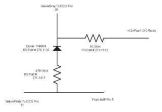
So you will see parts required are:
1 x 1N4004 diode
1 x 470 Ohm resistor
1 x 1K Ohm resistor
The wires we are interested in are:
Yellow/white (YL/WT) being the Pin 5 wire from the MAF to Pin 12 in the large ECU plug - Mass air flow sensor signal.
Grey/yellow (GY/YL) being Pin 2 in the EGR solenoid wiring plug - EGR solenoid control.
Red/light green (RD/LG) being Pin 1 in the EGR solenoid wiring plug - Fused auto shut down relay output.
The Merc wiring schematic refers mostly to ECU pin outs as they tend to take their wiring connections from the wires close to the ECU as their ECU plugs are different and easier to access. I did my wiring in the section of loom that is the wiring to the EGR plug.
You do not actually have to cut and disable any wires in this mod basically all you are doing is splicing into the applicable wires to add an override circuit if you like. How you achieve this is entirely up to you and in fact given the EGR plug is no longer connected if you really want you could cut that plug off and use the ends of those wires but the idea with this is if you want to re-enable the EGR you just plug the solenoid back in and snip your additional wires out.
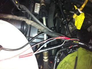
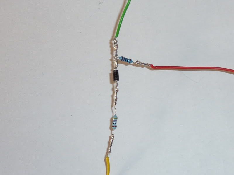
So I tracked the MAF signal wire (YL/WT) back through the loom to a point that was suitable to hack into. This was back near the point where the EGR wiring loom met back to the larger loom section. So I spliced a wire into the MAF wire and fed it through the loom to come out with the EGR wiring loom. This wire has the 470 Ohm resistor and diode in it as per diagram, note the diode is direction specific. This wire is then spliced into the Pin 2 (GY/YL) wire that is in the EGR loom. Then take another wire and splice it into the Pin 1 (RD/LG) wire which is the other wire in the EGR loom. This wire will have your 1K Ohm resistor in it and the other end then gets spliced into the new signal feed. As the picture shows they have it spliced into the new signal line from the MAF to the EGR signal wire aas long as it's upstream of the diode. I found it neater and easier to join it at the Pin 2 wire. What I did to make it secure was to put the wire with the resistor and diode into a strong tube, in my case I had an old sprinkler system riser tube laying around the ones that usually have micro sprayers on them. Then I heat shrinked the other wire with resistor to that and then conduited it back up and resealed the loom. The EGR loom and plug now just tuck in behind the solenoid out of harms way.
This is not quite how I laid out my wiring to fit the loom how I wanted but will give you a clear an simple visual of what we are talking about. No reason you cannot do it this way just up to you where and how you integrate it into your loom.
Now the disclaimers. The guys who introduced this mod and other wiring mods to the Merc forum are independent Merc based mechanics however they have prefaced this mod with the disclaimer that whilst they have tested it and it is working fine and not throwing any codes they offer it at vehicle owners risk. I might add hundreds have responded to the post and none have complained of issues. I have interpreted it to the best of my knowledge by cross referencing to the Jeep wiring manual and I have sought clarification from the Merc guys for minor descriptive variances in the terminology. I believe this how to is correct as there are only 3 wires relevent to the mod - The MAF signal wire is exactly the same as the Merc. The EGR signal wire which is a PWM switched earth has to be the same, leaving only the 12 volt feed. The 12 volt feed can be any ignition switched source and my understanding of the "fused auto shut down relay output" is that it is just that.
This from the Merc guys in response to my clarification: So you have the vacuum controlled EGR valve, using a modulator with 2 x wires? If so then yes, you have it about right. The valve has 1 x 12v, and 1 x switched earth (pulse width modulated - PWM). The duty cycle of the PWM signal leads the modulator to regulate EGR opening accordingly. You need the simple 3 x wire mod, with 2 x resistors and 1 x diode".
Now I clarify this and say you do this at your risk because the my vehicle is not up and running yet and has no battery power at all so I cannot test the 12 volt feed through the fused auto shut down circuit. Given the second wire of the EGR circuit is a 12 volt feed as quoted above I cannot see I am wrong however I have not been able to test the mod.
Hope this all makes sense. I've also done the swirl flap motor shunt to let the ECU think there is still a functioning swirl motor as mine was throwing a MIL fault for the swirl flaps before I powered it down. This wiring mod is also courtesy of the merc forum boys as this motor and the flaps fail quite a lot on the 3.0l motors.


 2014 Jeep KL

