Grand Willys Project - Page 287 - AUSJEEPOFFROAD.COM Jeep News Australia and New Zealand

Go Back   AUSJEEPOFFROAD.COM Jeep News Australia and New Zealand > JEEP GARAGE > Jeep build up
Register Forums Trading Your Jeep My Garage Mark All Read

Post New Thread  Reply
 
Thread Tools Search this Thread
  #2003  
Old 30-11-2022
LuluBelle's Avatar
LuluBelle  LuluBelle is offline
AJOR Bronze
 
Join Date: Apr 2013
Location: Blackall Outback Queensland
Posts: 1,736
What Jeep do I drive?: XJ
Likes: 1,286
Liked 947 Times in 637 Posts
Default

awesome work it has been a journey and love the furry friends pic
__________________
96 XJ Limited LPG Conversion......
99 XJ Sport ... Finally on the Road
RC Mini Me
Likes: (1)
  #2004  
Old 30-11-2022
Gojeep's Avatar
Gojeep  Gojeep is offline
LokRinger
 
Join Date: Jul 2002
Location: Victoria
Posts: 6,878
Likes: 792
Liked 1,768 Times in 560 Posts
Default

Many thanks.
__________________
Cheers, Marcus.

My web site:
http://willyshotrod.com Over 5'000 Club
  #2005  
Old 10-12-2022
Gojeep's Avatar
Gojeep  Gojeep is offline
LokRinger
 
Join Date: Jul 2002
Location: Victoria
Posts: 6,878
Likes: 792
Liked 1,768 Times in 560 Posts
Default


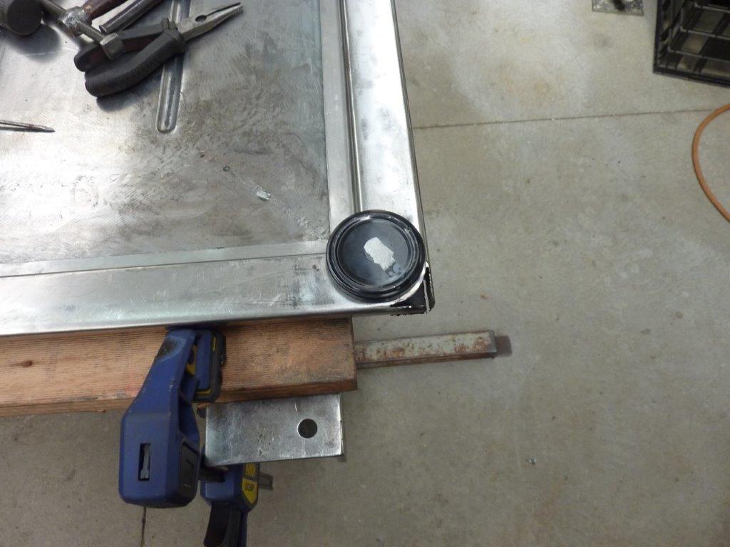
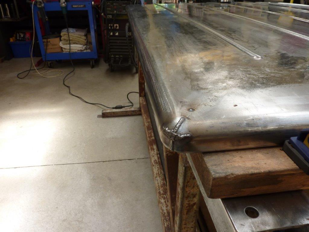
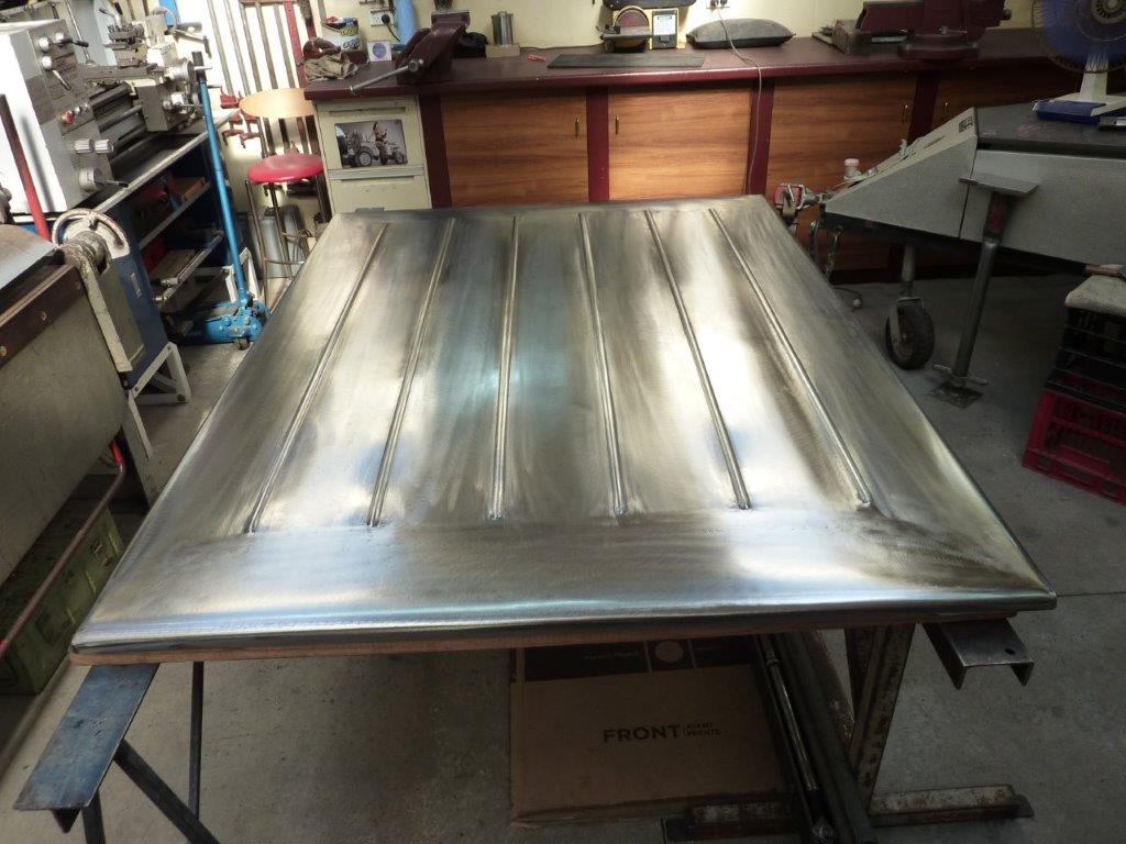
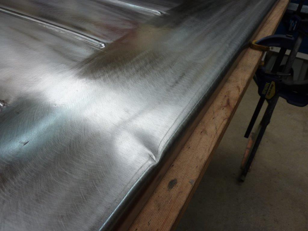
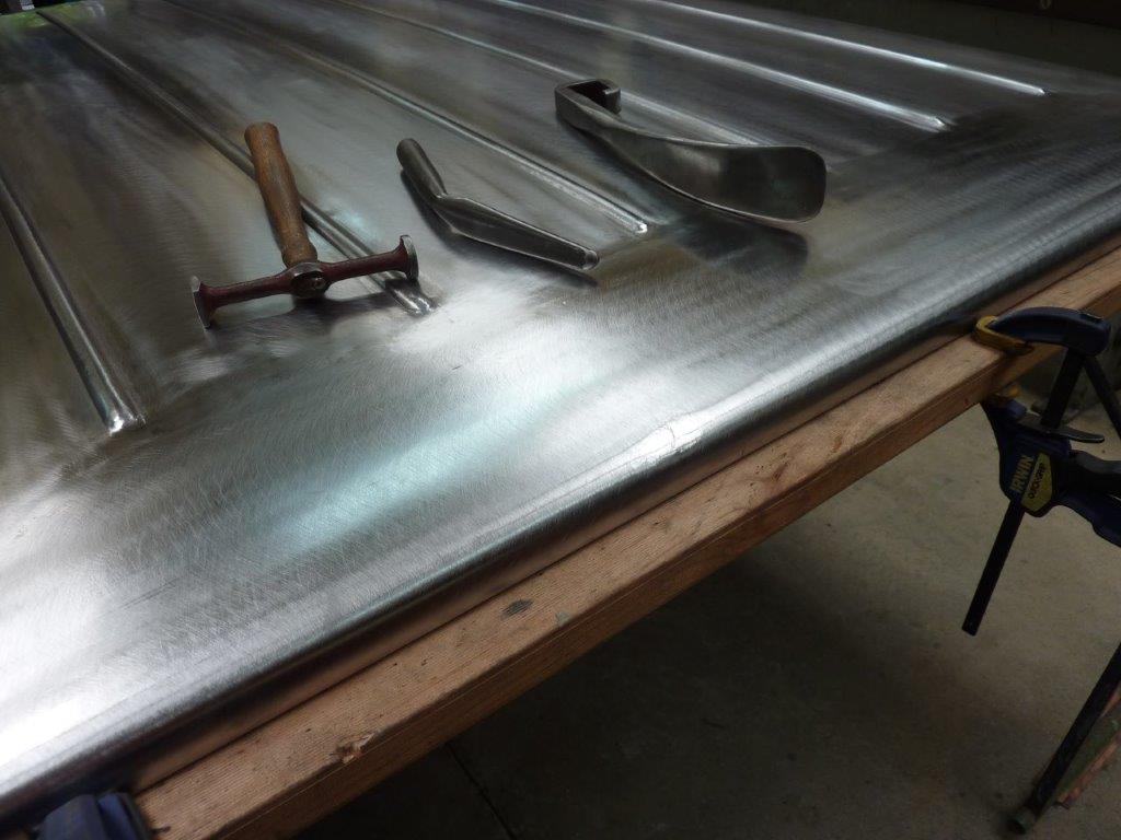
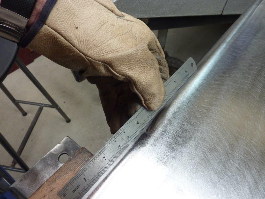
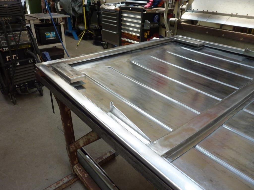
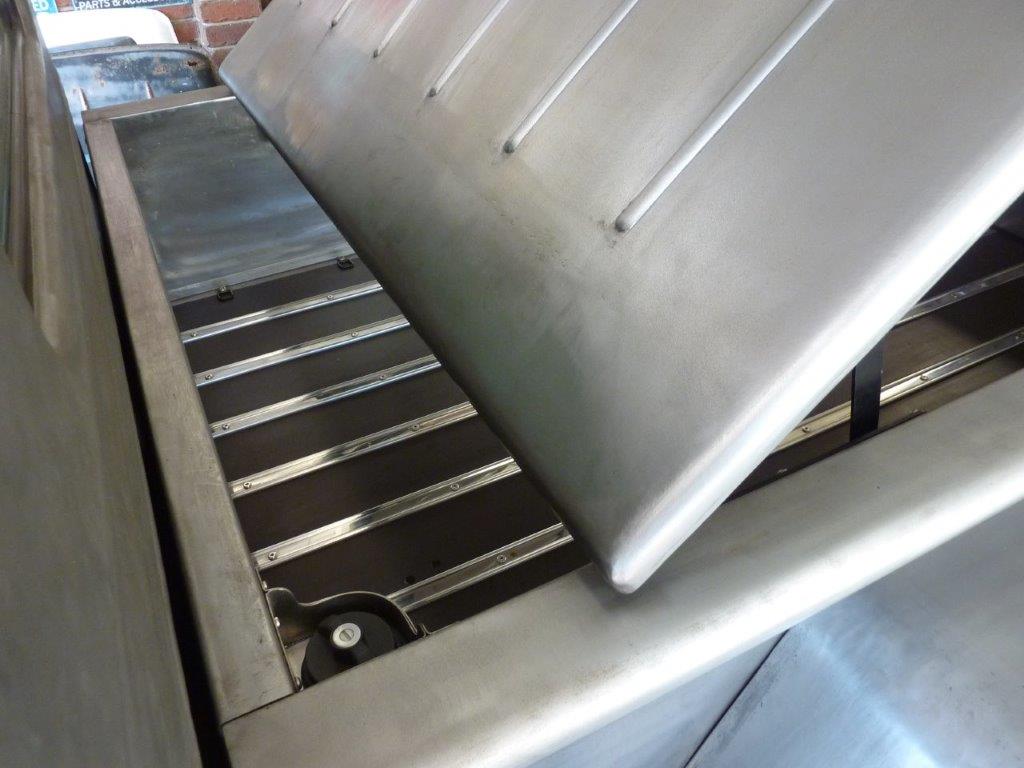
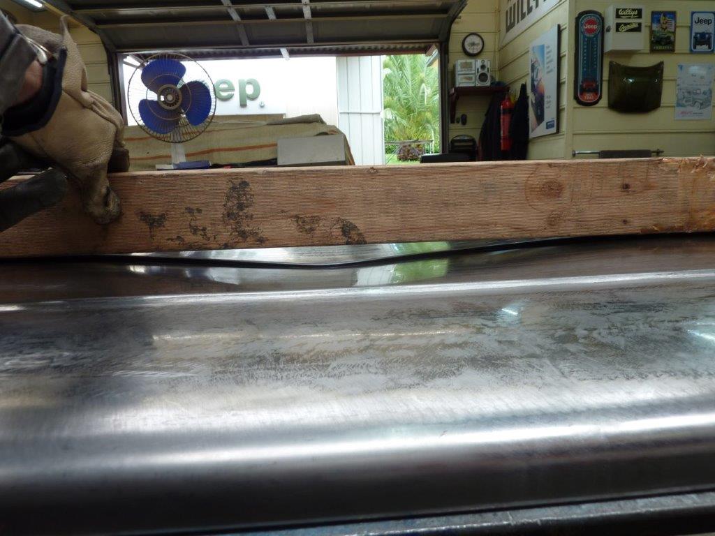
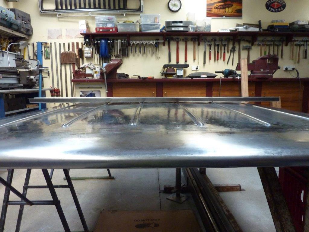
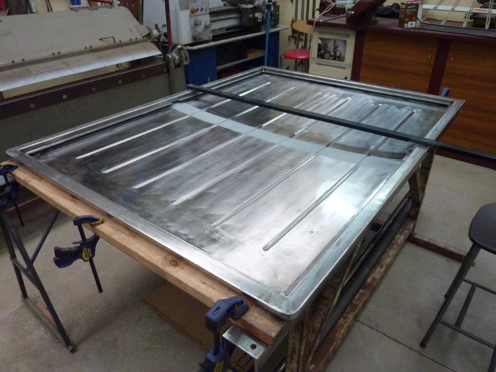
I noticed that a couple of the ribs were higher than they should be. This one was the worst at about 5mm-5/16". So I was heating it with a torch to a blue colour and suddenly it collapsed down in front of where I was heating. I think I was trying to heat too long a section at once. I used a bar dolly that matched the rib under it to knock it back up to level again before continuing on.


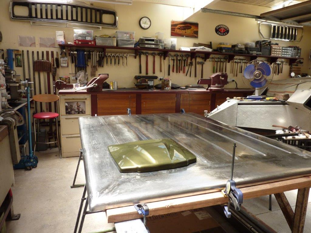
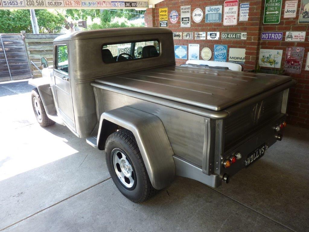
Laid my paint colour sample on it to give me some inspiration to keep at it. 
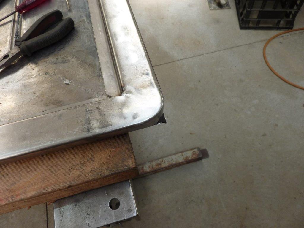
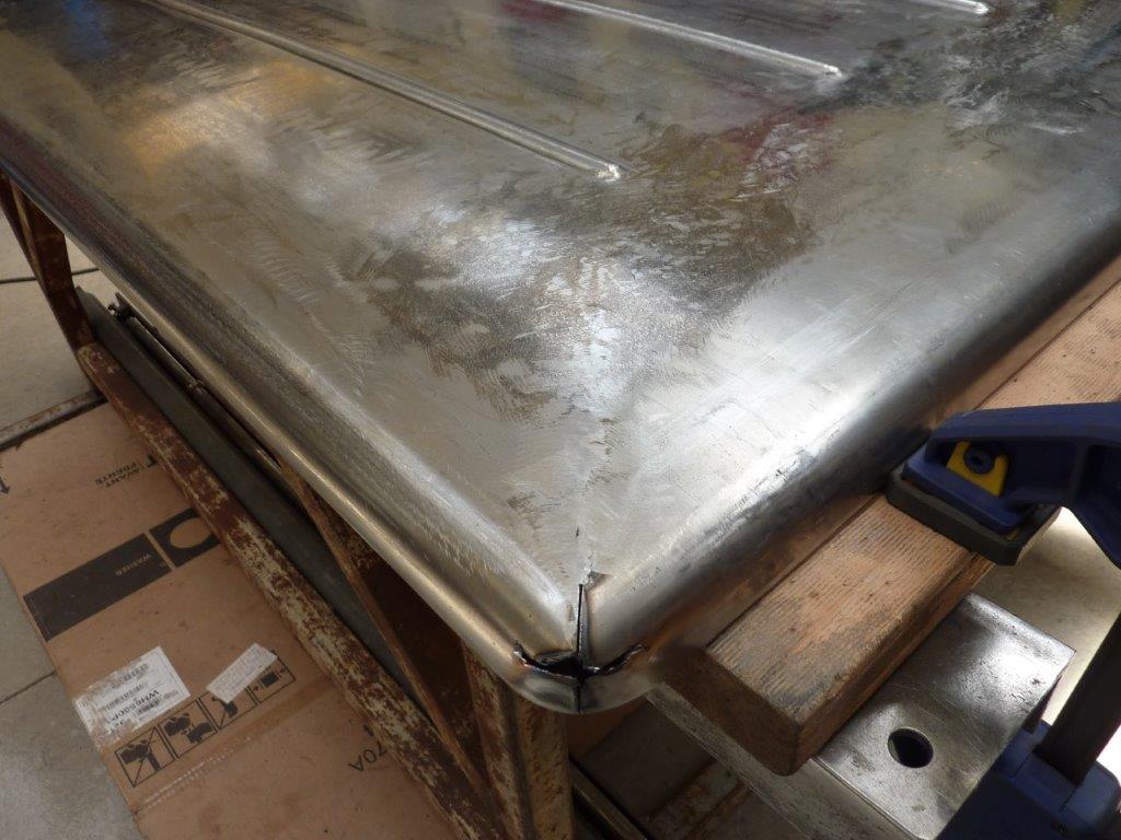
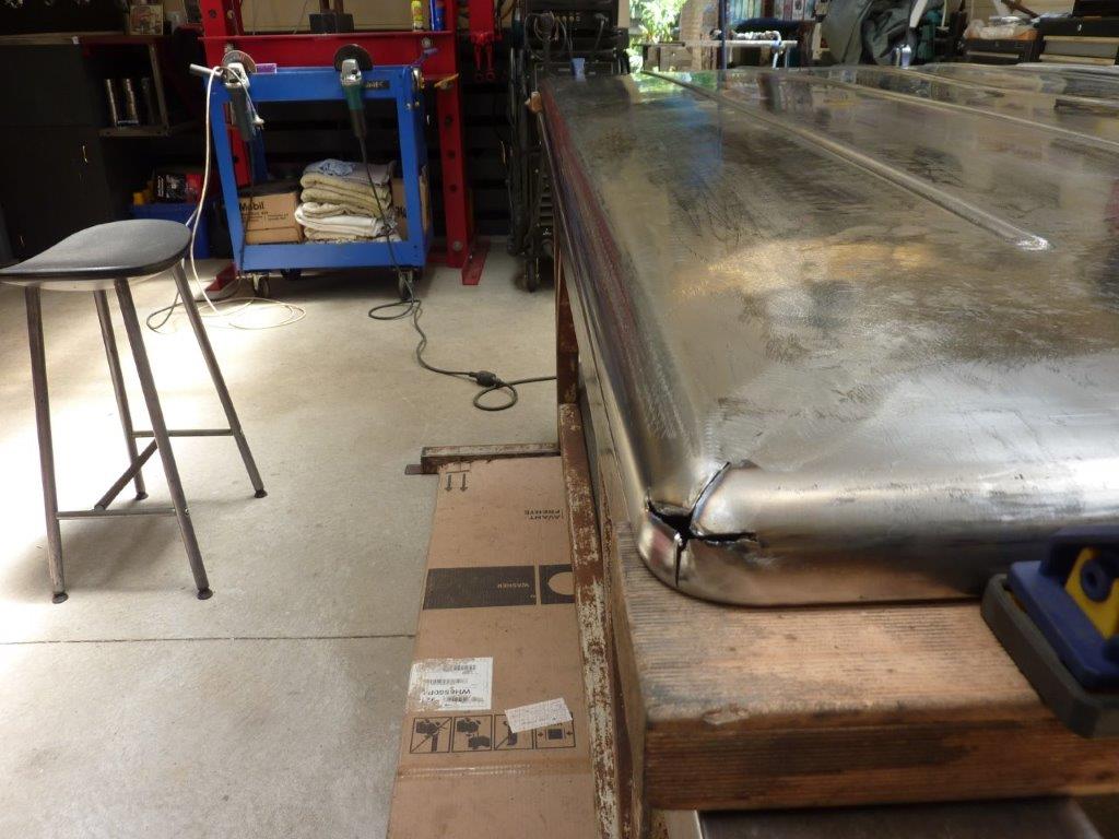
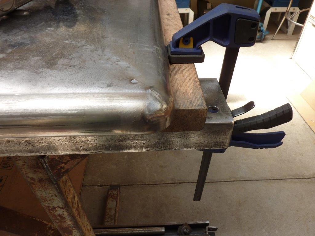
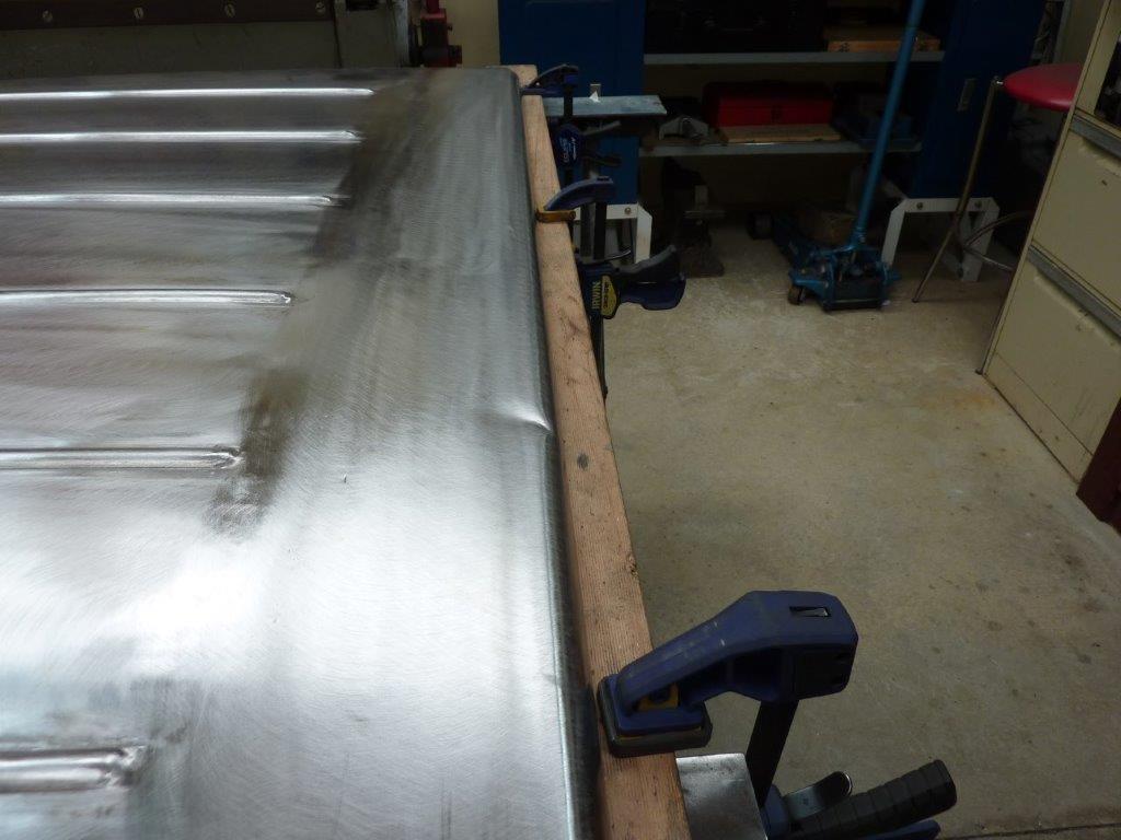
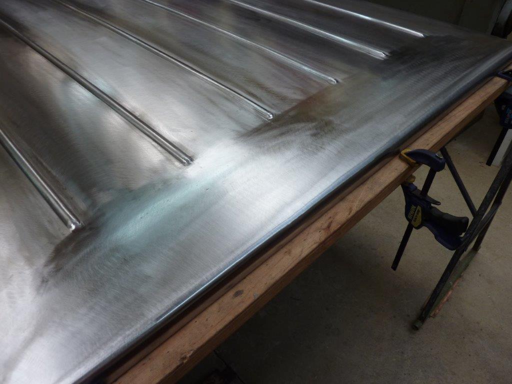
Can see how much of that rib I heated too. I was bringing the overall crown down more to make it look more factory.


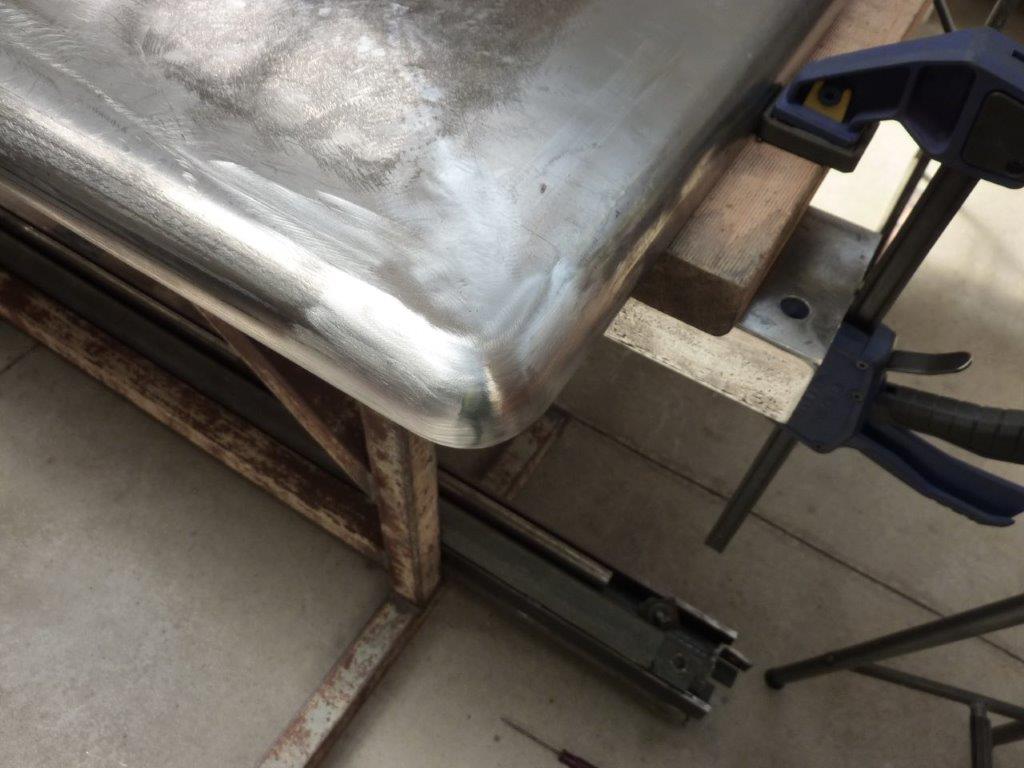
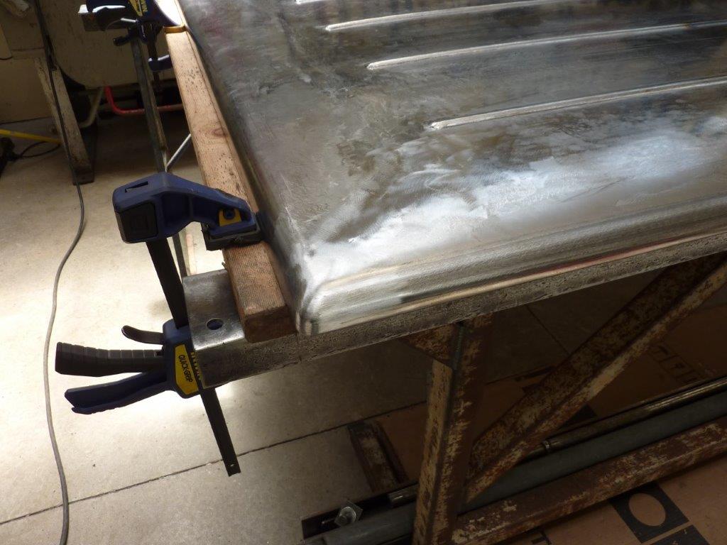
I noticed the side started bending inwards and upwards as well. Fortunately lowering the crown spread it back to where it was straight again, but caused the top of the skin to collapse! I tried the technique of hitting it down while it was hot, but it caused a lot of damage for me. I obviously need to be better at it. Went back to heating and letting it cool naturally which leaves the panel really tight in the area. I then hit it down off dolly or onto a lead filled rubber block to lower the high spot.


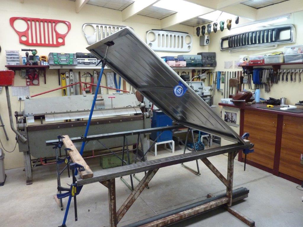
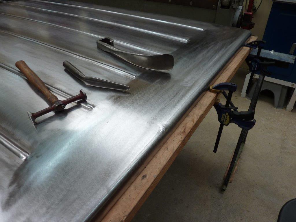
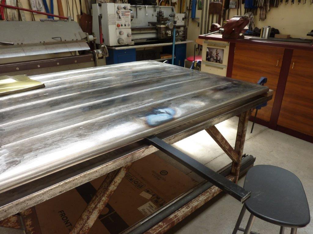
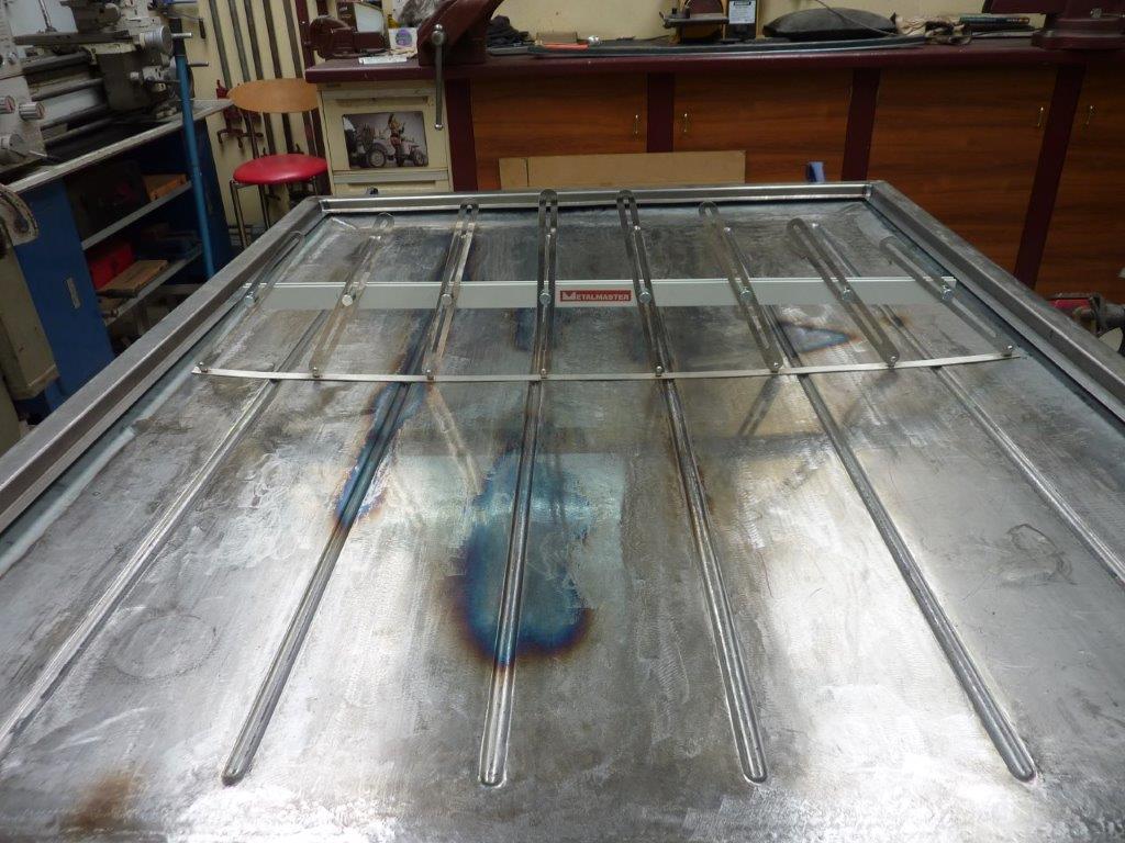
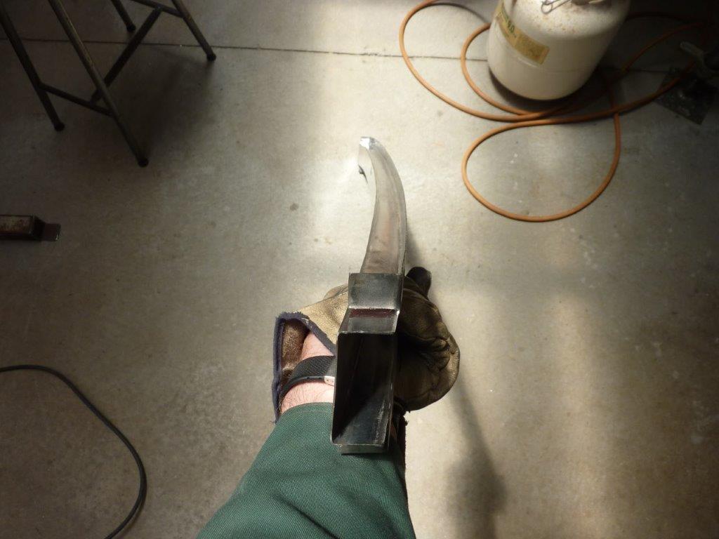
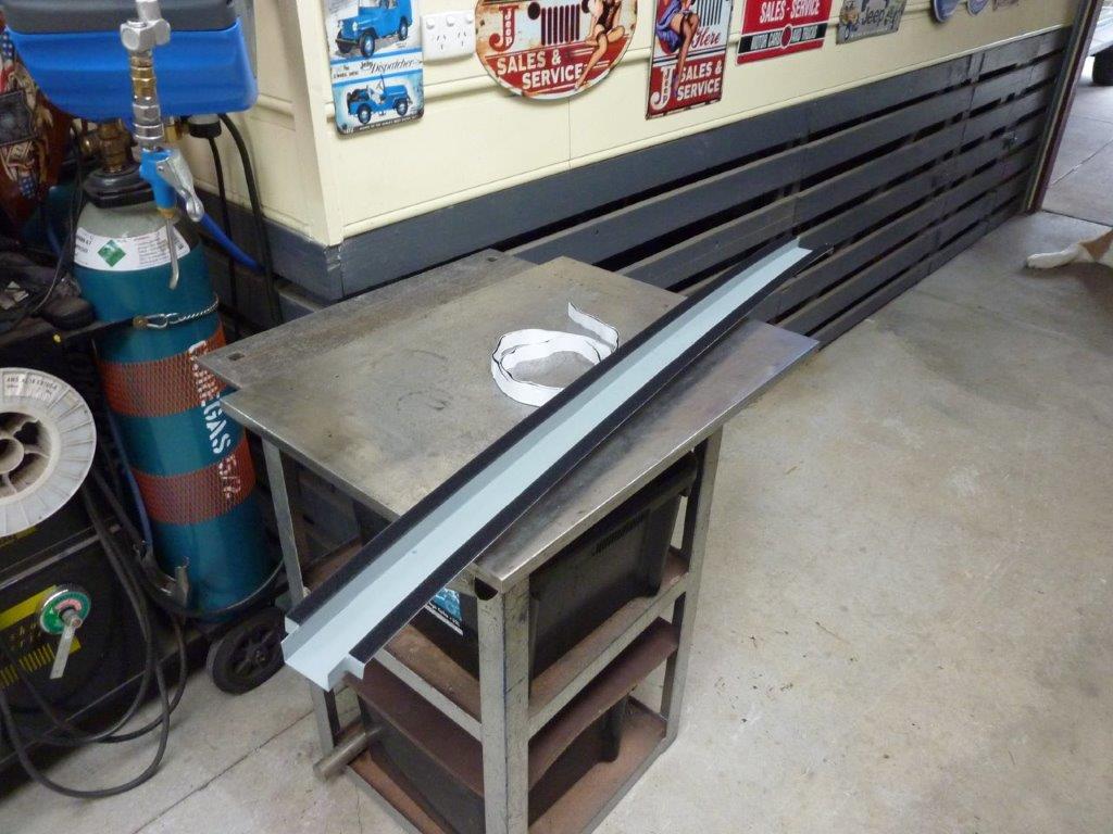
Once the crown was checked with the profile gauge left to right, front to rear, I could then make a centre crossmember. I folded up this hat channel and can see how much it needs to bend.


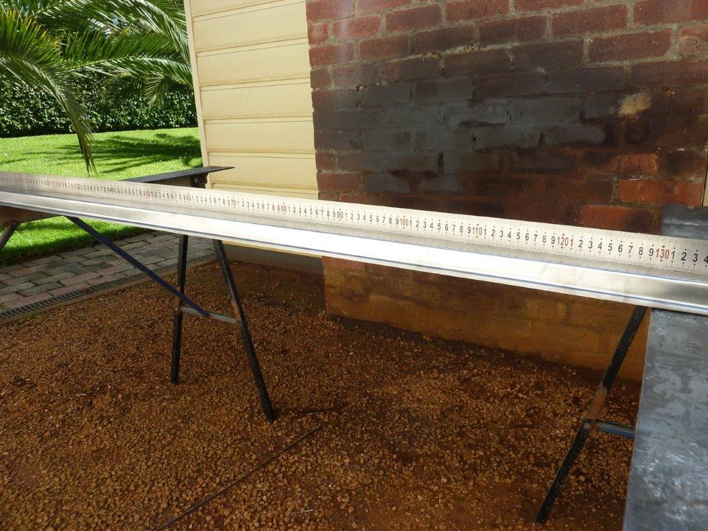
It starts out perfectly straight but needs a gradual curve to it to match the crown on the panel.


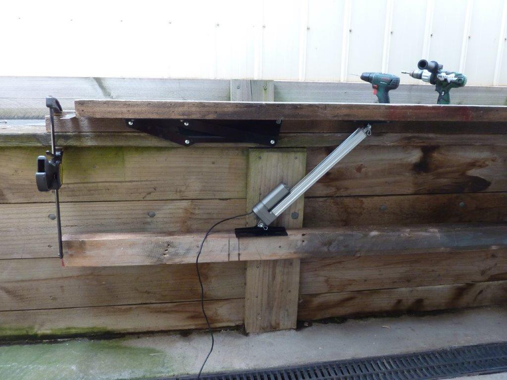
Using a propane torch I slowly just heated the top of it and let it cool naturally. Showing some good progress already.


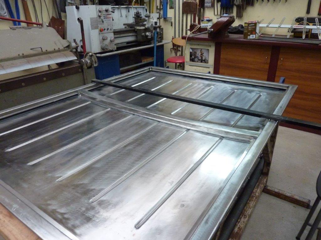
Can see the ends are about halfway closer now.


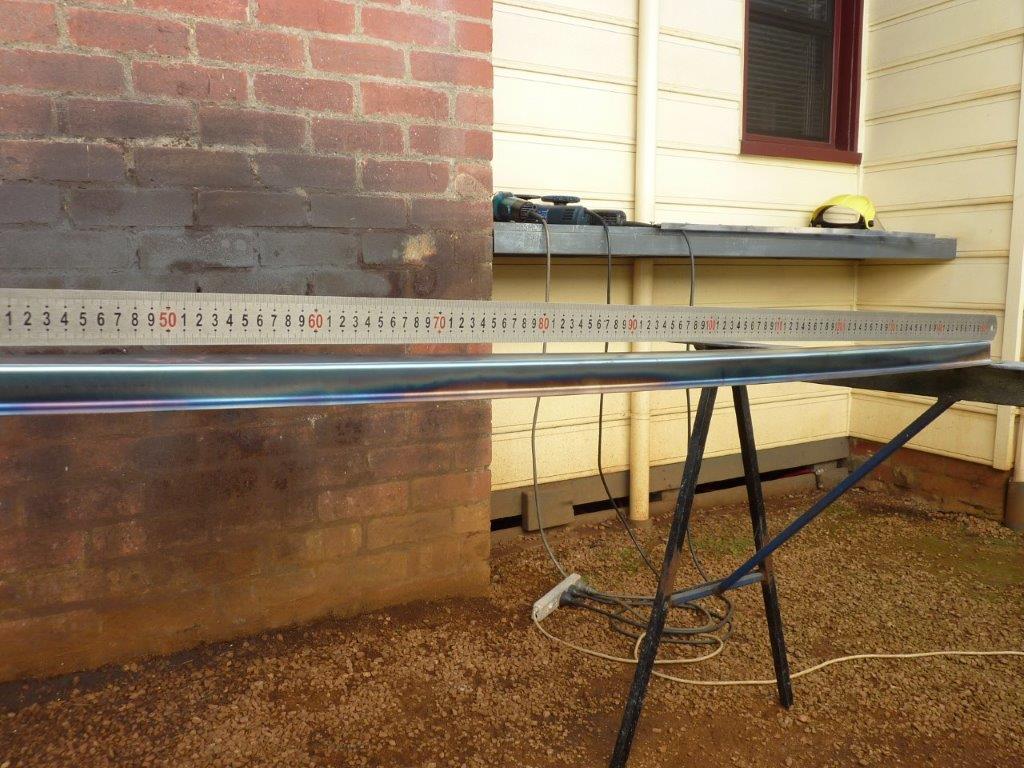
The curve needs to be more than the panel below it like it is already starting to show. One because there is more crown in the middle, but also it is the top surface of the crossmember that has to match.


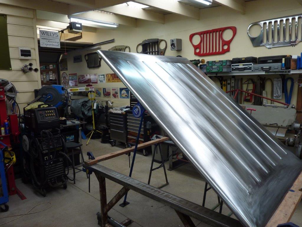
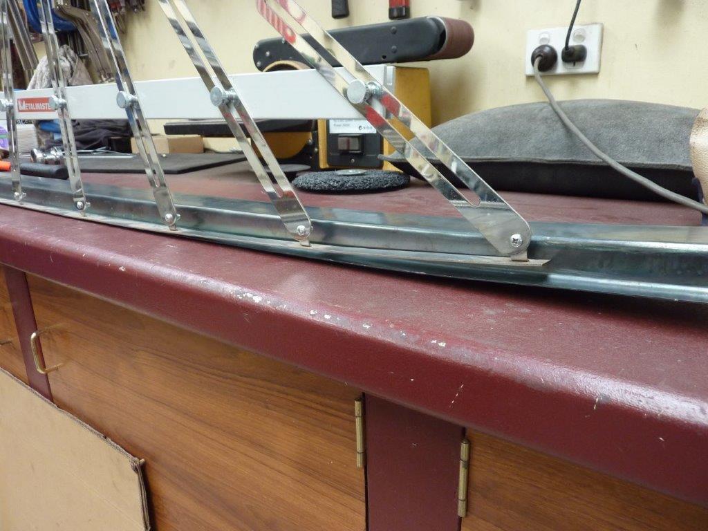
Time to take an accurate profile of where the crossmember will sit.


Can see it still has a little more to go. I tried the partial cut and weld back up method, but it was too harsh for such a gradual curve. So had to cut it and put it back to what it was.


The torch method was not getting it any further so actually placed a weld bead on the top edge where I needed to add the extra curve. The weld causes it to shrink and add more curve. Could place it in slightly different places left to right to get the curve perfectly even as well this way and was only needed near the ends where it was much steeper.


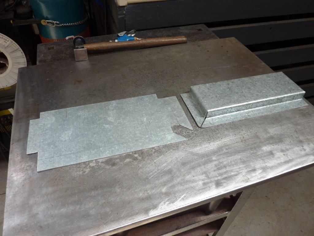
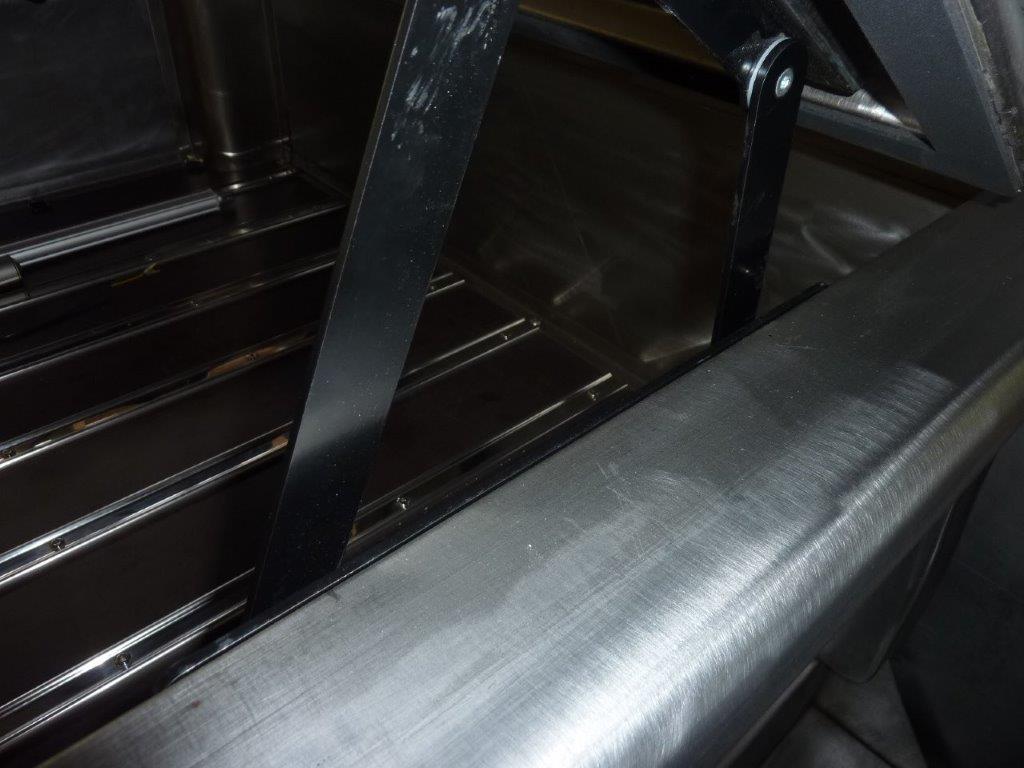
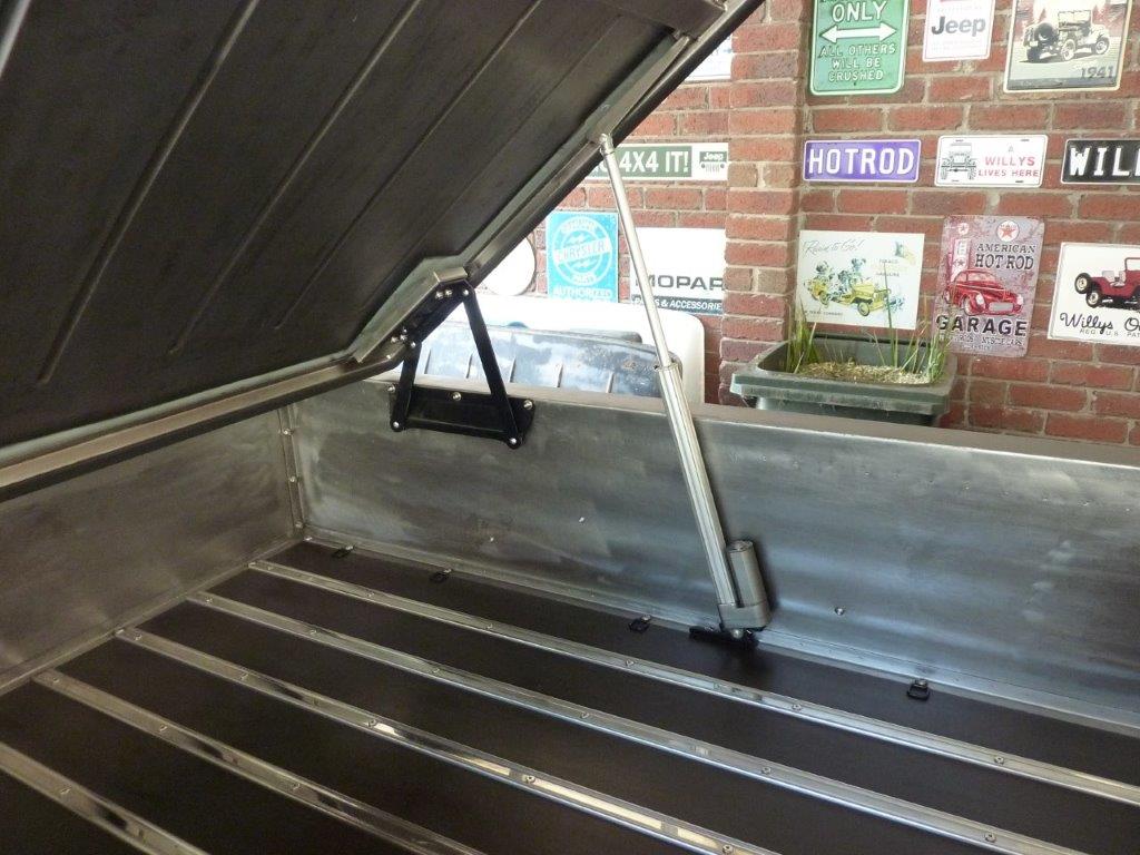
Prepping the area ready for the crossmember to go in. I left the brace in place to make sure the flanges didn't twist during welding or pull together.


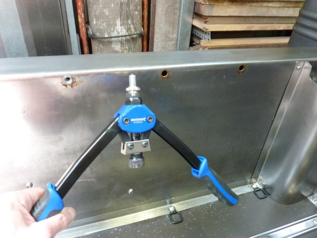
Here is a trick I picked up from Rod Covell from his old Street Rodder column where someone had said they had a problem with the adhesive between the roof panel and crossmember showing up in the reflections of their polished paintwork depending on the temperature of the day. Manufacturer's use this method on boots and bonnets etc, but the blobs of adhesive are quite thick and the frame is a good 5mm-5/16" away from the skin to help with the movement. So he said that he uses the loop/soft side of Velcro as a cushion to protect the paint from rubbing and to stop it rattling. I have used it with success on my roof crossmember as well.


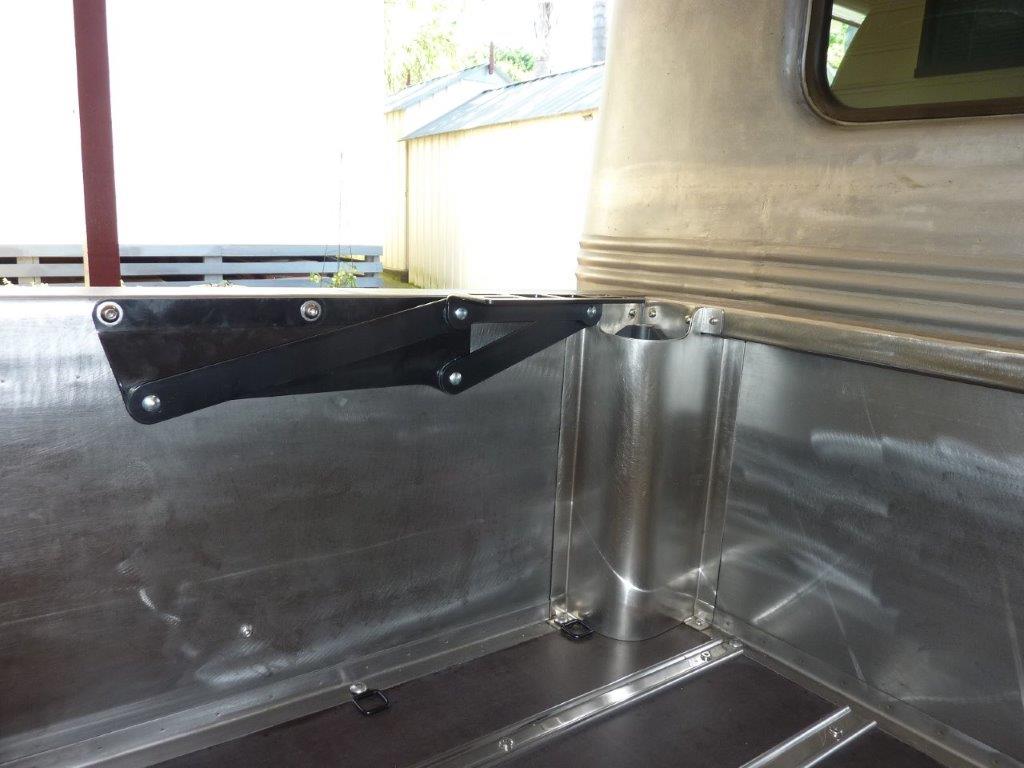
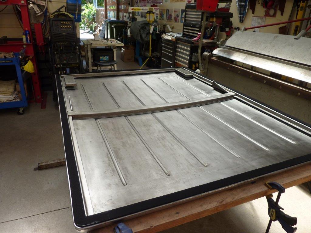
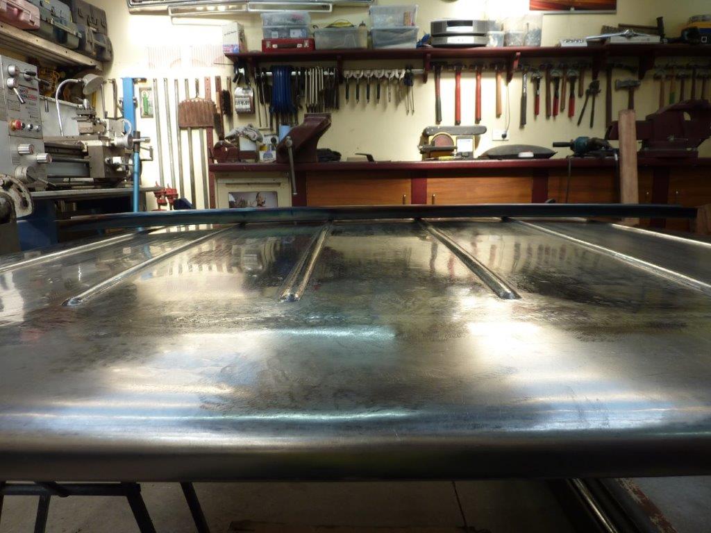
Crossmember dropped into place ready for welding.


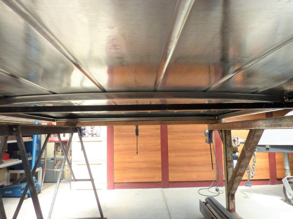
Follows the crown nicely.
__________________
Cheers, Marcus.

My web site:
http://willyshotrod.com Over 5'000 Club
Likes: (5)
  #2006  
Old 14-12-2022
Gojeep's Avatar
Gojeep  Gojeep is offline
LokRinger
 
Join Date: Jul 2002
Location: Victoria
Posts: 6,878
Likes: 792
Liked 1,768 Times in 560 Posts
Default


I never wanted the sharp corners on the cover which is why they were never welded. The plan was always to radius the tailgate end of the cover to be proportional to the radius at the end of the bedsides. The jam lid was just the right size and you can see how I have cut away the underside of the cover to match it and slot the vertical part of the sides.


I pulled the vertical parts around to follow the base.


From the top I could then make adjustments to the radius of the vertical part before bring the top down to meet it.


I slowly cutting a triangle out of each side of the very top part and tapped it down to give it a radius rather than a ridge.


Once it rolled over the curve I could weld it shut.


Ground it down to almost flush.


Then finished off with a flap disc.


At the cab end of the cover I just matched the radius to that of the ribs, as the bedsides are squared off at that end.


Every time I had been waiting for heat shrinks to cool, I was lifting the little low spots and planishing down the high ones. The final sand was just to remove the heat discolouration and most of the shrinking disc marks. I then followed with a 7" strip disc. I'm pleased with the way it has turned out and is exactly how I imagined it.
__________________
Cheers, Marcus.

My web site:
http://willyshotrod.com Over 5'000 Club
Likes: (5)
  #2007  
Old 24-12-2022
Gojeep's Avatar
Gojeep  Gojeep is offline
LokRinger
 
Join Date: Jul 2002
Location: Victoria
Posts: 6,878
Likes: 792
Liked 1,768 Times in 560 Posts
Default

Video update on building the hard cover for the Willys from scratch. https://youtu.be/DbQ809h9o90
__________________
Cheers, Marcus.

My web site:
http://willyshotrod.com Over 5'000 Club
Likes: (2)
  #2008  
Old 25-12-2022
Gojeep's Avatar
Gojeep  Gojeep is offline
LokRinger
 
Join Date: Jul 2002
Location: Victoria
Posts: 6,878
Likes: 792
Liked 1,768 Times in 560 Posts
Default


Working out how high we want it to raise. We settled on 40*.


40* should give us plenty of room around the hinge area to still get things in and out.


Making support mounts for the hinges to bolt too. The weird arrow shape is what you need if you have a step down and a flange and want it to fully meet in the corner.


I had been looking for some time to find a hinge like this that was a stronger version of a sofa bed hinge where it lifts up and back at the same time.


Upside down to the way it will mount, but you get the idea of how the pivot point raises and moves backwards


Well third time unlucky? Is that a thing? Turning it over to fit the new hinge mounts and it slipped right off the trestle again and put an even sharper dent this time on the new end piece.


Hurts more as thought I was done with the panel work!


Couldn't use the same spoons as last time as was higher up in the radius. Shaped the end of the small one to do 95% of the work. No hitting from the underside as inside the frame area. Getting most of it our levering and tapping down the high spots at the same time.


Almost there now and no filing, sanding done at all. Just the three tools above and taken about 30 minutes.


Got it raised and the polished area is just from the hammering and nothing else. The crease is right by the 4" mark.


There was a little bit of stretch from the impact so a quick pass over it with the shrinking disc and then a light sand and strip disc. Barely tell it ever happened.


Well I had given up hope of using electric actuators to lift the cover as all I had seen were so slow! Then we saw a setup on a Ford XR6 Ute at the Sandown show we had taken the Truck too. Asked him if he could demonstrate it and it was so much faster! Not only that but had the hinges I had been looking for as well! So doing setup trials here to see how to mount the actuators and still get the lift angle we were after. Turns out this didn't work well as you used a lot of the travel as the hinge pivot moved forward with the actuator extending. So flipped it to work with the actuator base away from the hinge so the hinge pivot is getting closer to the actuator as it raises.


So now have plugged welded the hinge supports in as well as the actuator pivots.


To attach the hinges to the bed sides I'm using 8mm Nutserts. Notice a good deal of wax to help stop rust in the hole and under the head.


I stepped the back of the hinge holes in for the Nutsert flange to sit in.


I have placed the hinge just back from the the fuel filler so I don't have to alter that.


Can see here how it bolts up flush against the sides. This is the company I bought the hinges, actuators, remote controller and harness from: https://www.flat-top-products.com.au/


So using neoprene self adhesive seals to keep the water and dust out along with setting the same 4mm-5/32" gap I have for all my panels. Got the protective wax on too ready for fitment.
__________________
Cheers, Marcus.

My web site:
http://willyshotrod.com Over 5'000 Club
Likes: (3)
  #2009  
Old 26-12-2022
Gojeep's Avatar
Gojeep  Gojeep is offline
LokRinger
 
Join Date: Jul 2002
Location: Victoria
Posts: 6,878
Likes: 792
Liked 1,768 Times in 560 Posts
Default


First time on there so finally get a chance to see what it looks like. Not once was the cover on until finished!


Very happy with the profile and it's everything I hoped it would be. Suits the proportions of the whole truck.


Now you can see too why I wanted the type of hinges I used. Look how easy it is to fill the tank and put things in and out at this end of the bed. Will build a custom box later to fit in there.


I used this calculator to see how the different angles changed the load requirements on the actuator. Linear Actuator Calculator | FIRGELLI Automations You enter the size of the box and lid angle and weight, (mine came out to 24.8kg-55lbs), and work out the position and capacity of the actuators. Basically the further from the hinge and the more vertical the actuator is mounted, the less force you need. If you had a fixed pivot, (which I don't), you can plot the exact spot to mount it.


As you can see, 40* is more than enough. What is great using actuators over gas struts is it is not trying to push it upwards, breaking the seal against the bed, when closed. I adjusted it to put some tension on holding the lid down before it shuts off. A drive on poor roads into the country showed it didn't bang or flutter at all at speed, so really pleased with the outcome. No lift handle or locks penetrating the skin are also needed for a better, cleaner and more waterproof result.


To fully raise it takes just 14 seconds and 10 seconds to go back down. Speed ratings are for unloaded and these came out at 45mm, (1.75") a second. Others I see are only between 3 and 8mm, (0.1-0.3") a second! So with 350mm of travel these have it would take over 2 minutes to raise it with the slower actuators.


I just took it to the service station to fill the tank and it is up before you get around to taking the cap off. You just let it go down as you walk off to pay.
__________________
Cheers, Marcus.

My web site:
http://willyshotrod.com Over 5'000 Club
Likes: (4)
Post New Thread  Reply


Posting Rules
You may not post new threads
You may not post replies
You may not post attachments
You may not edit your posts

BB code is On
Smilies are On
[IMG] code is On
HTML code is On


All times are GMT +10. The time now is 03:59 AM.


Advertisements


AJOR does not vouch for or warrant the accuracy, completeness or usefulness of any message, and are not responsible for the contents of any message. The messages express the views of the author of the message, not necessarily the views of AJOR or any entity associated with AJOR, nor should any advice be substituted as technical advice replacing that of a mechanic. You agree, through your use of this service, that you will not use AJOR to post any material which is knowingly false and/or defamatory, inaccurate, abusive, vulgar, hateful, harassing, obscene, profane, sexually oriented, threatening, invasive of a person's privacy, religious, political or otherwise violative of any law. You agree not to post any copyrighted material unless the copyright is owned by you or by AJOR. The owner, administrators and moderators of AJOR reserve the right to delete any message or members for any or no reason whatsoever. You remain solely responsible for the content of your messages, and you agree to indemnify and hold harmless AJOR, the administrators, moderators, and their agents with respect to any claim based upon transmission of your message(s). The use of profile signatures to intentionally mislead or misdirect any member on this forum is not acceptable and may result in your account being suspended. Any trip that is organised through the AJOR forum is participated at your own risk. If you or your vehicle is damaged it is your responsibility, not that of the person that posted the thread, message or topic initiating the trip, nor the organisers of AJOR or moderators of any specific forum. This forum and associated website is the property of AJOR. No user data is harvested and no information supplied in your registration will be sold for profit.


Powered by vBulletin® Version 3.8.7
Copyright ©2000 - 2024, vBulletin Solutions, Inc.

AJOR © 2002 - 2024 AUSJEEPOFFROAD.COM. All corporate trademarked names and logos are property of their respective owners. Ausjeepoffroad is in no way associated with DaimlerChrysler Corporation or Fiat Jeep.
www.ausjeep.com www.ausjeep.com.au www.midlifemate.com ausjeepforum.com www.r9kustoms.com
vB Ad Management by =RedTyger=